the calculation for power is as follows....p=(2x power xR)..square root the total...then divide the answer by the square root of 2(1.414)to get the ACv of the secondary.... so 2x200 x8=3200..sq root of 3200=56.5vdc then divide by 1.414=40v AC...
That's for a 100% efficiency output stage and perfect power supplies. Most amps will loose 10 - 15% and supplies will sag a couple volts. 45VAC will probably put out around 180W RMS at clipping.
imho he will need more psu voltage ...one of my leach amps with 2x 45V ac - reaches max. approx. 135W @8R ...
That's either a really inefficient amp or very saggy supplies. I haven't built the Honeybadger but I did build it's big brother, the Slewmaster with Wolverine inputs. It's output was 180W with 45VAC secondaries which produced +/- 63VDC rails.
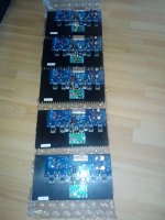
5 channel ?
hello, sorry, I didn't follow the forum lately, I saw well, did I build a 5 channel bad badger? sorry that used transformer? thanksJust had to check the diodes.
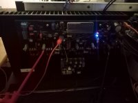
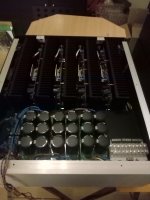
DC protection LED's comes on one at the time in i nice row from left to right.
Hi all, I am new to this thread. Is there an LTSPICE schematic of the Honey Badger (and associated models)? I would like to give it a go in Simulation before building it. Also, I would like to use it as a base of experimentation to try some ideas.
NOTE: I have also posted this question in the main Honey Badger thread.
Thanks!
- Sandro
NOTE: I have also posted this question in the main Honey Badger thread.
Thanks!
- Sandro

Finnished the PSU tonight. But i had to change out the transformer. The first one had a lot of hum. But i had 2 of them. Now it's silent. PSU outputs +/-56.7Vdc with 224V mains.
Which producer made that transformer? Once I had to return Talema transformer purchased from RS. It would be good to know which brands should be avoided as I intend to buy now two 1kVA 2x50V TRIAD toroids (VPT100-1000) from mouser. TRIAD I think is located in Sri Lanka. I wonder if anyone here used TRIAD toroids.
cheers,
It's a Talama from RSI'll think a stick to toroidy from now on.
So it was Talema again. I heard that toroidy make good toroids. For you shipping costs should be acceptable but for me shipping costs probably would cause my heart jump.
cheers,
A tiny bitty hickup. Powered up the first ch to night to get some music playing.
and i noticed it was a lot of noise. Thinking it might be my source, i powered it back down and the negative rail puse blew. i reconnected my source and changed the fuse. Powered it back up, and both positive and negative rail fuses blew.
i do have continuity between positive and negative connection. Between output and positive AND negative. And between E and C on all output devices. Also on cross of positive and negative devices. No cuntinuity between sink and any outputlegs, or gnd to positive, negative or output. But output impedance is around 75 Ohm. Also ofcourse 75 Ohm between posite and gnd, and negative and ground.
any idè??
EDIT: Conductivity. not continuity.A tiny bitty hickup. Powered up the first ch to night to get some music playing.
and i noticed it was a lot of noise. Thinking it might be my source, i powered it back down and the negative rail puse blew. i reconnected my source and changed the fuse. Powered it back up, and both positive and negative rail fuses blew.
i do have continuity between positive and negative connection. Between output and positive AND negative. And between E and C on all output devices. Also on cross of positive and negative devices. No cuntinuity between sink and any outputlegs, or gnd to positive, negative or output. But output impedance is around 75 Ohm. Also ofcourse 75 Ohm between posite and gnd, and negative and ground.
any idè??
Tonight it happend again. 2 other ch went boom. this time they blew the positive rail fuse. both at the same time. while playing music at low volume. the only component i could think of that is able to couse this is, D4 and D5. So i cut one leg of each and the problem is gone. All output seams fine. but why would this happend? they are soldered the correct way. So i checked my shoppinglist. The diodes are 40V pieces *banging my head agains the wall*
Last edited:
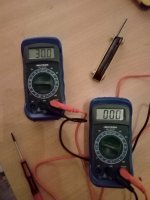
i used a series lamp dim bulb tester so that in case of mistakes, you do not let the magic smoke out..you will need this to confirm output offset voltage is much much lower than +-100mV, and that bias is adjustable, once confirmed these two criteria, you can remove that and fine tweak the bias, adjust the bias when heatsinks have warmed up, occasionally backing it down to target bias...notice that bias tends to go up as the heatsink gets warmer, so back it down a notch...
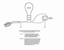
those bulbs are unobtanium over here. esyer to get genuine SJ74 J-fets but the offset and bias is correct. It was all in place. But i will readjust on all amps once more.
the bias actualy went down as the sinks got warmer. about 2-4c above ambient. failure of D4 and D5 vil not alter the bias or offset. it was just that it was to much voltage for that device. so it past it's voltage to the next rail and blew the fuses.
but the offset and bias is correct. It was all in place. But i will readjust on all amps once more.the bias actualy went down as the sinks got warmer. about 2-4c above ambient. failure of D4 and D5 vil not alter the bias or offset. it was just that it was to much voltage for that device. so it past it's voltage to the next rail and blew the fuses.
Last edited:
that would be after playing for full volume for a a hole bunch of hours. somthing that would never happend. You can not set the bias for a temperatur that demands å full volume playing for 3-4 hours. i bet the sinks can get up to 50 C at a loud volume for some hours
I did have the bias stable for around an hour or so for each ch.
Besides. i did tune it "cool" at just 70mA. so i have a lot to og on.
I did have the bias stable for around an hour or so for each ch.
Besides. i did tune it "cool" at just 70mA. so i have a lot to og on.
Last edited:
- Home
- Amplifiers
- Solid State
- diyAB Amp The "Honey Badger" build thread