Hi All.
I would like somebody to confirm that the input differential pairs degeneration resistance is approximately 83.33 ohms.
As R16 is 100ohms and half of R17 is 500ohms.
100ohms in parallel with 500 ohms is 83.33 ohms.
Is this correct?
Yes, it is correct
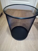
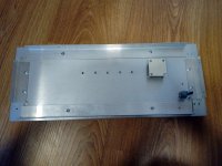
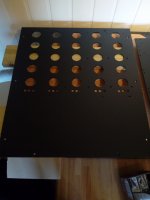
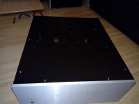
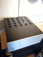
Finnised the top lid to day. 5x35mm + 3x9mm vents pr heatsink.
The wiremesh came from a paper trashbin")
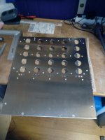
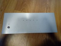
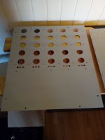
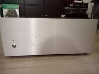
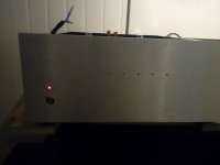
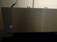
I also got around to finnish the front panel. Just missing the LED's.
The wiremesh came from a paper trashbin
I also got around to finnish the front panel. Just missing the LED's.
Attachments
Wow. I did not realise this at first. This then means that the emitter degeneration is only 7:1. With the LTP current source set to 3.75mA as recommended by the build guide.Yes, it is correct
I calculate the following. Maybe someone can check these numbers for me to.
re' = Vt / Ic
Ic = 3.75 / 2 => 1.875
re' = 26 / 1.875
re' = 13.87 ohms
Emitter degeneration = (Re + re' / re')
Emitter degeneration = (83.33 + 13.87) / 13.87
Emitter degeneration = 7
Isn't 10:1 usually recommended as it provides better linearization of the input differential pair and better local negative feedback to Q1 and Q2 admittedly at the cost of some IPS gain.
I was looking at this because I wanted to have some idea what the gain crossover frequency of this amplifier was.
I have not seen any specifications published for this amplifier.
So maybe someone can check these numbers for me to.
Gain crossover frequency (Fc) = 1 / 2 x pi x Rltp x CLG x CM
Rltp = (83.33 + 13.87) x 2
Rltp = 194.4 ohms
Closed Loop Gain (CLG) = (R6 + R5) / R5
Closed Loop Gain (CLG) = (33000 + 820) / 820
Closed Loop Gain (CLG) = 41.24 or 32.3db
Miller Capacitor (CM) = 100pf
Gain crossover frequency (Fc) = 198,520 hz
And finally Slew rate (SR) equals
I = C * dv/dt
SR = 37.5V / uS
So slew rate would equal 37.5V /us
Last edited by a moderator:
Emitter degeneration = (Re + re' / re')
Emitter degeneration = (83.33 + 13.87) / 13.87
Emitter degeneration = 7
ah, the rule of 10, if the Re is greater than re by 10 or more......i agree here...since the Re dominates....
Leach used 270 ohms Re with tail current of 4ma.....
ah, the rule of 10, if the Re is greater than re by 10 or more......i agree here...since the Re dominates....
Leach used 270 ohms Re with tail current of 4ma.....
I guess that we can do it more accurately to work with the current emitter resistor that we have.
We can transpose and rearrange the following two formulas to caculate Ic.
1. re' = Vt / Ic
2. Emitter degeneration (Ed) = Re + re' / re')
So the result using the current resistor values and a emitter degeneration of 10 becomes
Ic = Vt x (Ed -1) / Re
Ic = 2.8mA
This will then required a new calculation for the appropriate values for C7 + C8
I guess that the point of my last post was to check that the Gain crossover frequency is caculated correctly.
Last edited:
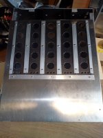
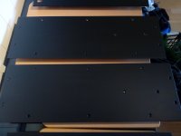
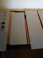
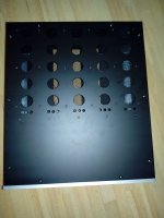
Got some painting done. 1 layer of primer on both sides. And 1 layer of paint on the inside, and 2 layers of paint on the outside. Just missing the bottom panel and brackets.
Attachments
Hasn't any specifications for this amplifier ever been posted.i remember Leach Super amps had a 800khz Fc...
Can anyone confirm that the gain crossover frequency (Fc) for the honey badger is about = 198,520 hz
Seams a bit low to me would have thought that it was at least 500khz.
You must have very, very good ears!
Best regards!
Its not about good ears its about amplifiers stability, phase margin and calculating the Miller Capacitor.You must have very, very good ears!
Best regards!
Hasn't any specifications for this amplifier ever been posted.
i read that from the 1980 Audio article written by Leach detailing his design considerations then....that was a construction article but was very detailed in treatment of theory behind his amp, the super leach....that article should be in the net somewhere...
i can not speak for the honey badger, i haven't read any about its open loop gain crossover frequency, i suspect they would be higher given the higher Ft devices used in the design compared to the 1980's leach amps than used the 2n3440...
i am sure this was discussed in the development of the design by Pete V. just don't have the time dig up...
a cornering frequency, say in the 20khz region would be best as far as Leach wrote...
i am sure this was discussed in the development of the design by Pete V. just don't have the time dig up...
a cornering frequency, say in the 20khz region would be best as far as Leach wrote...
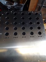
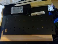
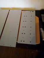
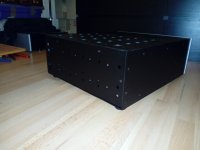
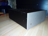
The chassis is comming together. Don't mind the glitch on the backpanel. That will be gone as sone as the heatsinks are in place.
Attachments
What supply voltage would i have to run to hit 200-210W into 8 ohms? ive been looking at these boards for a couple years now and now im getting back into it
the calculation for power is as follows....p=(2x power xR)..square root the total...then divide the answer by the square root of 2(1.414)to get the ACv of the secondary.... so 2x200 x8=3200..sq root of 3200=56.5vdc then divide by 1.414=40v AC...
- Home
- Amplifiers
- Solid State
- diyAB Amp The "Honey Badger" build thread