Hi,
I'm testing 1 channel of the HB amp. Here are the settings of the trimmers.
All transistors have been installed. I am using the lightbulb approach to limit the current. I've adjusted the R30 until i got around 20mV on TP1 and TP2.
Can I connect a speaker directly to test it out? I have a pre-amplifier which can be attached to the input, connected to a DAC and Chromecast Audio as source.
So, howabout a venue size switch, like a DPDT on/on, to change the speaker return point from the technically correct small venue return point, or as-needed to the high-current large venue speaker return point?
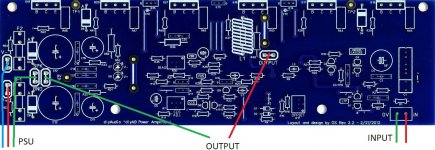
The signal ground should be returned to the load ground and then to the local PCB star ground. Please observe the attachment which shows a PCB of a measured (THD <0.004%) low distortion amplifier. Note that the signal ground on the left meets the speaker (load) ground in the very center of the board and then only returned to the local star ground on the bottom of the board.
Professional PCB designers never return the signal and load grounds to different locations as this will easily lead to more distortion and noise due to error voltages developing.
On a side note the V+ and V- traces are right next to each other to reduce loop area mediated distortion. The loop area vectors mediated by the Upper (V+ related) and lower (V- related) portions of the LTP and VAS too cancel each other out too. This is a good PCB design.

Last edited:
Hi guys,
I'm also confused about the correct grounding layout for the HB.
Having a look at Bob Cordells Star on Star diagram 16.8

Would it be correct to do the following:
Speaker return to amp board
Signal return to amp board
Capacitor midpoint on power supply to amp board ground point
Then connect TP0 on amp board to safety earth.
This configuration would follow Bobs 16.8 diagram the best and be a star on star ground.
It seems most advice so far to approximates Bobs 16.1 diagram

i.e.
Make power supply capacitor junction the star ground point and connect everything to it including safety ground. No one seems to connect signal return directly to power supply star ground. Instead signal return goes back to the amp board and then would eventually connect via the power supply ground and about 5 ohms of resistance through the pcb.
Firstly am I on the right track, does my interpretation of 16.8 make sense?
Why doesn't anyone recommend returning signal return to all the way to the power supply? This would match the 16.1 diagram best.
Which is better out of the two options described?
Is there a good image of the chassis ground wiring that I can just follow so i can finish the amp.....
I'm also confused about the correct grounding layout for the HB.
Having a look at Bob Cordells Star on Star diagram 16.8
Would it be correct to do the following:
Speaker return to amp board
Signal return to amp board
Capacitor midpoint on power supply to amp board ground point
Then connect TP0 on amp board to safety earth.
This configuration would follow Bobs 16.8 diagram the best and be a star on star ground.
It seems most advice so far to approximates Bobs 16.1 diagram
i.e.
Make power supply capacitor junction the star ground point and connect everything to it including safety ground. No one seems to connect signal return directly to power supply star ground. Instead signal return goes back to the amp board and then would eventually connect via the power supply ground and about 5 ohms of resistance through the pcb.
Firstly am I on the right track, does my interpretation of 16.8 make sense?
Why doesn't anyone recommend returning signal return to all the way to the power supply? This would match the 16.1 diagram best.
Which is better out of the two options described?
Is there a good image of the chassis ground wiring that I can just follow so i can finish the amp.....
I see 5 pin power devices. What are these? Do they contain temperature sensing diodes (ThermalTracks)? If so, why's there also this BD139 Vbe multiplier?
Best regards!
Yes, they are the NJL3281 thermal track devices. The thermal track transistors diodes by themselves alone proved inadequate for thermal bias stability despite the datasheet claims, therefore it is necessary to use them together with a traditional vbe multiplier (bias spreader) to achieve thermal stability. They are generally placed in series with the traditional vbe multiplier. The tracking diodes introduce the temperature effects of the output transistors, while the vbe multiplier transistor takes care of controlling that part of the bias spread necessary for the predriver and driver transistors.
I am of the understanding that in this method the vbe multiplier transistor should NOT be mounted on the heatsink as it should have nothing to do with thermal bias, so i am thinking that it was a error of the silicon chip design to mount the bd139 on the heatsink.
Bob Cordell talks about this a lot in his book designing audio power amplifiers. I have copied the image below from his book, i hope he does not mind it as it is to show the method.

Last edited:
Hi guys,
Would it be correct to do the following:
Speaker return to amp board
Signal return to amp board
Capacitor midpoint on power supply to amp board ground point
Join signal ground to speaker (load ground) and then to local PCB star ground. Local on board PCB decoupling capacitors grounds are joined together and then returned to the local PCB star ground as well. Return the local PCB star ground to the main power supply decoupling capacitors ground.
The best location for the mains earth wire to be grounded with the chassis ground would be the input signal ground.
I see this arrangement in most low distortion designs to minimize ground loops and hum.
Regardless, the only real way to get immunity from ground loops and hum is to use a fully differential input stage.
Last edited:
Hi guys,
I'm also confused about the correct grounding layout for the HB.
Having a look at Bob Cordells Star on Star diagram 16.8
View attachment 749651
Would it be correct to do the following:
Speaker return to amp board
Signal return to amp board
Capacitor midpoint on power supply to amp board ground point
Then connect TP0 on amp board to safety earth.
This configuration would follow Bobs 16.8 diagram the best and be a star on star ground.
It seems most advice so far to approximates Bobs 16.1 diagram
View attachment 749661
i.e.
Make power supply capacitor junction the star ground point and connect everything to it including safety ground. No one seems to connect signal return directly to power supply star ground. Instead signal return goes back to the amp board and then would eventually connect via the power supply ground and about 5 ohms of resistance through the pcb.
Firstly am I on the right track, does my interpretation of 16.8 make sense?
Why doesn't anyone recommend returning signal return to all the way to the power supply? This would match the 16.1 diagram best.
Which is better out of the two options described?
Is there a good image of the chassis ground wiring that I can just follow so i can finish the amp.....
I believe this is what was intended by the designer.
Attachments
I cover this issue in my ground loops write-up (see link below).
If you run the speaker return wire back to the amplifier module PCB, the important thing is to have good bulk decoupling on the amp module PCB, and it needs to be wide band. That way, you end up with only LF speaker currents in the 0V wire from the amplifier to the PSU star ground - the HF currents are trapped on the module through the bulk decoupling.
If you decide you want to run the speaker return back to the central start ground, just twist it with the speaker hot and then run it (twist if you can) with the 0V supply connection. There will be a short section that will not be coupled to either the speaker hot or the 0V to the PSU, but it should still be ok.
From my experimentation, it seems practically there is not much between the two - if and only if - your amplifier module board decoupling is good, which is pretty easy to do.
Happy building
")
If you run the speaker return wire back to the amplifier module PCB, the important thing is to have good bulk decoupling on the amp module PCB, and it needs to be wide band. That way, you end up with only LF speaker currents in the 0V wire from the amplifier to the PSU star ground - the HF currents are trapped on the module through the bulk decoupling.
If you decide you want to run the speaker return back to the central start ground, just twist it with the speaker hot and then run it (twist if you can) with the 0V supply connection. There will be a short section that will not be coupled to either the speaker hot or the 0V to the PSU, but it should still be ok.
From my experimentation, it seems practically there is not much between the two - if and only if - your amplifier module board decoupling is good, which is pretty easy to do.
Happy building
in my amps, safety ground is connected to the nearest netalwork, i.e. in one of the screws holding the IEC socket screws...
i do not connect the main star grounding of the psu direct to chassis, but where the signal is lowest, via the input jacks and thru a low ohm resistor....
i have done amps using plastic casings, and grounding was never an issue...
i do not connect the main star grounding of the psu direct to chassis, but where the signal is lowest, via the input jacks and thru a low ohm resistor....
i have done amps using plastic casings, and grounding was never an issue...
Wow. Thanks John. Such a great idea I'm really impressed with this pcb.Hi Stu, they are the transistor mounting screw heads seen through holes in the PCB. All the transistors mount underneath the PCB to save heatsink realestate.
i moved the last two post to a new thread with due respect to this one...https://www.diyaudio.com/forums/sol...R7DcilWawwO98sHfOXLxIzV5yTx7X4V7KHpsMVbRjg4dA
Thanks Tony. Great Idea to start a new thread.i moved the last two post to a new thread with due respect to this one...https://www.diyaudio.com/forums/sol...R7DcilWawwO98sHfOXLxIzV5yTx7X4V7KHpsMVbRjg4dA
Honey Badger amplifier completed
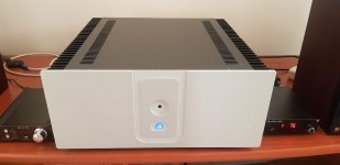
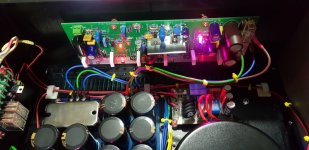
Thanks to everyone who have contributed to this forum, I managed to build this amp without burning any components. I've set the bias to around 30mV for R30 and with the large heat sinks, I am able to keep the heatsinks hot but not too hot that I cannot touch them.
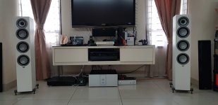
The sound of the amp is amazing. I compared it to my old Marantz PM7200 and Arcam alpha 6 plus amplifies, all 5 star amps on WHat Hifi, this amp makes the music soundstage so much more appealing. I played my music through Elac Unifi F5 slim floorstanders which were 4 ohm speakers.. and the amp didnt have any issues controlling the Elacs.
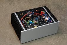
Here are some photos of my amp.
Thanks to everyone who have contributed to this forum, I managed to build this amp without burning any components. I've set the bias to around 30mV for R30 and with the large heat sinks, I am able to keep the heatsinks hot but not too hot that I cannot touch them.
The sound of the amp is amazing. I compared it to my old Marantz PM7200 and Arcam alpha 6 plus amplifies, all 5 star amps on WHat Hifi, this amp makes the music soundstage so much more appealing. I played my music through Elac Unifi F5 slim floorstanders which were 4 ohm speakers.. and the amp didnt have any issues controlling the Elacs.
Here are some photos of my amp.
Attachments
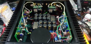
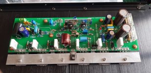
Best Badger yet. Very nice output stage implementation.
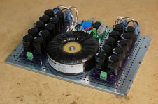
VERY ample PS , too!!
Mine has even more caps in the PSU!
Rail voltage is abot +/- 40 VDC only in mine. Works great, though!
Attachments
- Home
- Amplifiers
- Solid State
- diyAB Amp The "Honey Badger" build thread