One channel caught on fire. The power supply is +/-62vdc and the output transistors are Toshiba 2SA1302/2SC3281 purchased about 15 yrs. ago from a US distributor. After some research I believe the 1302's are fake, and failed. What do you other builders think?
Damn i thought US distributors have good quality control cause everything is overpriced there! I thought that money goes to quality control and checking authentic products.
HIFI101, I thought so too. I bought those transistors many years ago, long before I was aware of the problem of fake parts. So I used them and experienced the failures. After researching on the internet, youtube videos and Rod Elliot's fake transistor article, I determined that the 1302's were fake. I have since taken this forum's advise and will use OnSemi transistors from Digikey, Mouser, Arrow, ect., to repair my Badger amps and for future builds. Also, when I get back to working on the Badgers, I will remove the 22 ohm resistors R53 and R54 as I believe they caused the severe damage to the pcb.
Hi Guys,
I thought that I might post a slightly clearer version of the HB schematic so others can benefit from studying the layout and each of the circuit building blocks.
Maybe some one else can give it a quick check to see if its correct.
I am thinking that I will in the future highlight / circle and name each of these circuit building blocks to help other learn how the circuit works.
Attachments
Hi Guys,
I thought that I might post a slightly clearer version of the HB schematic so others can benefit from studying the layout and each of the circuit building blocks.
Maybe some one else can give it a quick check to see if its correct.
I am thinking that I will in the future highlight / circle and name each of these circuit building blocks to help other learn how the circuit works.
Good stuff. You might reconsider the GND symbol used in the schematic, see here. Some people get really crazy over that (I don't).
Hi Guys,
I thought that I might post a slightly clearer version of the HB schematic so others can benefit from studying the layout and each of the circuit building blocks.
Maybe some one else can give it a quick check to see if its correct.
I am thinking that I will in the future highlight / circle and name each of these circuit building blocks to help other learn how the circuit works.
I think that Baker clamp is missing?
Best regards!
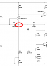
IMHO: C7 should not be connected to R25 and collector of Q9....
Maybe some one else can give it a quick check to see if its correct.
...
C7 should be connected to C8 and R24 only.
BR, Toni
Attachments
Thanks for pointing that out miss that when I checked it myself.Hi Stuart
C7 is incorrectly connected according to the original schematic.
Please correct your drawing, so it doesn’t create confusion.
Thanks
Harry
What about the answers from Germany and Austria?Thanks for pointing that out miss that when I checked it myself.

Hi Stuart
C7 is incorrectly connected according to the original schematic.
Please correct your drawing, so it doesn’t create confusion.
Thanks
Harry
Thanks again Guy's please let me know if there is anything else.
Maybe a moderator can remove the last PDF file to save confusion like Harry kindly pointed out.
Attachments
What about the answers from Germany and Austria?
OK OK Big thanks to the Australians - no I meant Austrians!
You are correct about the BAV21.
Yes you are both correct D10 should be a BAV21. I just checked my Digikey order from back in 2017 and that's what I ordered. I guess my idea of the schematic was more the layout and correct component identifiers. I would assume that the forum moderator would keep the bill of materials up to date. However I am happy to make any changes as it will all help in the end. I'll update the schematic again when I get a chance.OK OK Big thanks to the Australians - no I meant Austrians!
You are correct about the BAV21.

Have a simple question, might have been asked before but it is a rather large thread.
If i want to increase / Decrease the power of the amplifier is it as simple as Adding/Removing a transistor pair (Q19,Q21).
Or does values need to be changed or a new design of the circuit?
If i want to increase / Decrease the power of the amplifier is it as simple as Adding/Removing a transistor pair (Q19,Q21).
Or does values need to be changed or a new design of the circuit?
Well each transistor has a limit to how much can be used. if you can increase/ decrease the amount of transistors to balance out the load on each transistor. for example if i want to use 600W the transistors will sooner or later let out the magic smoke. and if i use 50W 3 transistor pairs might be to many if i want to save in on components if i only need 1 pair.
If you use 1 pair or three pairs with the same voltage power supply the amplifier will try to put out the same amount of power, it will just blow up faster with less output devices. Supply voltage needs to be lowered to lower maximum output power.
If supply voltage is lowered a lot then usually some other areas need to be altered to compensate. VAS current needs adjustment usually and input CCS or regulator can also need retuning.
If supply voltage is lowered a lot then usually some other areas need to be altered to compensate. VAS current needs adjustment usually and input CCS or regulator can also need retuning.
- Home
- Amplifiers
- Solid State
- diyAB Amp The "Honey Badger" build thread