designing and picking out caps for the power supply
Since this is my first amp build have some questions about designing and picking out caps for the power supply which will be complete dual mono with dual soft starts, 400VA( 45VAC secondaries )...
1: Is there any harm in going with bigger capacitance than the recommended in build guide? (I could probably fit caps up towards 100kuF per channel in the chassi)
2: What kind of ESR on the caps should i be aiming at? I have found these *Link to mouser*KEMET Caps*Link to mouser* that has 22mOhm ESR. Would they be suitable for a HB power supply?
3: After reading about different grounding techniques I'm thinking that the channels should have separate star grounds with a ground loop breaker for each of them(and power inlet ground straight to chassi). Is that good thinking or could someone give some some advice of how it could be done?
I'm very greatful for any kind of advice regarding the psu / build.
/Ejje
Last edited:
1: Is there any harm in going with bigger capacitance than the recommended in build guide? (I could probably fit caps up towards 100kuF per channel in the chassi)
The more, the better

2: What kind of ESR on the caps should i be aiming at? I have found these *Link to mouser*KEMET Caps*Link to mouser* that has 22mOhm ESR. Would they be suitable for a HB power supply?
Lower ESR is always better, but I wouldn't worry too much. There are some local buffer caps on the HoneyBadger board, and that's where ESR matters in my opinion. You could also use several caps in parallel, which will give a lower total ESR.
3: After reading about different grounding techniques I'm thinking that the channels should have separate star grounds with a ground loop breaker for each of them(and power inlet ground straight to chassi). Is that good thinking or could someone give some some advice of how it could be done?
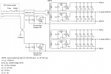
Yes, that's the way to go. I attached a schematic of how I built the power supplies of my Honey Badgers.
If you're using loudspeaker protection units at the amp output, make sure to keep the GND separated between the two channels. Some protection units have a common GND for both channels. Even if using two separate protection units (one per channel), be careful not to connect the two GNDs via the helper power supply of the two protection units.
Attachments
... Yes, that's the way to go. I attached a schematic of how I built the power supplies of my Honey Badgers.
If you're using loudspeaker protection units at the amp output, make sure to keep the GND separated between the two channels. Some protection units have a common GND for both channels. Even if using two separate protection units (one per channel), be careful not to connect the two GNDs via the helper power supply of the two protection units.
Thanks for your answer! I will be using dual speaker protection boards so i'll be sure to keep GNDs separate
I see you didn't use any pi-resistors/CRC configurations, i cant say I understand the use or can calculate the proper values for them(i just bought a bunch of 0.47Ohms 3W incase i should use them since this seems to be a regular value). Would i be missing out of something if I didn't use them?Hi Ejje,
Actually, using huge amounts of capacitance doesn't help you for one. For two, you end up with HF noise from diode switching. If you are dead set to use huge amounts of capacitance, then you are further ahead putting a bunch in parallel. You're going to have to use larger rectifier diodes as well since your hot switching current will be much higher.
When improving the sound of equipment for clients, I am often in the position where I have to reduce the amount of capacitance. Just use a reasonable amount of capacitance as specified by the designer. Using more doesn't buy you anything but problems.
-Chris
Thanks for your answer! I will be using dual speaker protection boards so i'll be sure to keep GNDs separate
CRC (or CLC) configurations are good as ripple filters in situations where a constant current is drawn from the power supply. This is the case with most class-A amps, but not with the HoneyBadger (class-AB). I wouldn't use a CRC (or CLC ) with the HoneyBadger.
... you end up with HF noise from diode switching ... You're going to have to use larger rectifier diodes as well since your hot switching current will be much higher.
Snubbers will remove those switching/ringing issues (see the schematic in my pevious post).
When improving the sound of equipment for clients, I am often in the position where I have to reduce the amount of capacitance. Just use a reasonable amount of capacitance as specified by the designer. Using more doesn't buy you anything but problems.
That's interesting. My experience is the opposite: adding more capacitance to the power supply is usually good, and has never had a negative effect so far. My first PSU for my HoneyBadgers (on the bench) had some 10 or 20 uF per rail (don't remember exactly). The larger capacitor bank in the final build substantially improved the sound quality.
Hi Ejje,
Actually, using huge amounts of capacitance doesn't help you for one. For two, you end up with HF noise from diode switching. If you are dead set to use huge amounts of capacitance, then you are further ahead putting a bunch in parallel. You're going to have to use larger rectifier diodes as well since your hot switching current will be much higher.
When improving the sound of equipment for clients, I am often in the position where I have to reduce the amount of capacitance. Just use a reasonable amount of capacitance as specified by the designer. Using more doesn't buy you anything but problems.
-Chris
Okey, I guess I will have to try adding and removing caps to find what works best
Thanks for you input!I see, good to know. I guess I wont be using the resistors after allCRC (or CLC) configurations are good as ripple filters in situations where a constant current is drawn from the power supply. This is the case with most class-A amps, but not with the HoneyBadger (class-AB). I wouldn't use a CRC (or CLC ) with the HoneyBadger.
The higher the first filter capacitance, the smaller the diodes' conducting angle, the higher the peak current. Average current will stay the same at a given load, though, but we need to observe the diodes' peak current ratings and possibly the transformer's core saturation.
Best regards!
Best regards!
The higher the first filter capacitance, the smaller the diodes' conducting angle, the higher the peak current. Average current will stay the same at a given load, though, but we need to observe the diodes' peak current ratings and possibly the transformer's core saturation.
Best regards!
Okey, thats beyond my knowledge of diods and transformers..
This is the bridge rectifiers I'll be using.
(*Link to mouser*)
"Max Surge Current: 400 A"
"If - Forward Current: 35 A"
They should be able to handle some beating right?
I haven't seen any datasheets for my transformers. They are the "audio grade model" (*Link to Toroidy*)
Find the total of all the secondary circuit resistances.
Find the open circuit secondary voltage.
Ipk = V/{total of secondary resistances}
But this is what happens when closing a switch on the secondary side after the transformer has already started. It is a worst case.
In practice the transformer secondary develops a rising output as the core flux builds during the start up phase. This gives a slowing effect to the initial charging current.
Hi Kay Pirinha,
And that is my point exactly. There is usually a "happy point" where you have more than enough capacitance for the job at hand. Going beyond that typically causes various troubles. The use of a soft-start circuit helps the initial surge current, but the continuous charge pulses is called "hot switching current". This is what you need to be careful of. Those short duration peak currents can generate the hash, or noise that can be picked up by other circuits.
Hi Ejje,
It is generally okay to increase capacitance by 20% or so, but over that wouldn't be recommended. Any changes related to greatly increasing capacitance is generally an artifact of expectation bias. This is assuming a competently designed device with a reasonable amount of supply capacitance. There are times when excessive capacitance will actually help a poorly designed device, but correcting bad engineering with more bad engineering isn't generally going to result in a good balance for performance.
-Chris
Hi everyone, I have just purchased the Honey Badger boards and ordered most of the board components. I also ordered the UPS boards, I have a 1000VA 230V , 55V+55V toroidal transformer which I would like to use, is this too much? Should I order something with lower output voltages? I see from previous posts that the highest secondary voltages quoted for this build( that I have seen) are 45V.
The Honey Badger can use 35Vac, or 40Vac transformers. You might get away with 30Vac to allow very high bias currents.
There may be some reports on using 45Vac transformers. You will need to search to see how successful they were.
55Vac is far too high.
Mine is one of the 45V builds. It is still not assembled. Hopefully once I've finished installing my floors I will get a chance
. I believe the build guide uses a similar 800VA - 45v x 2 to what I am using. Random advice: If I had my time back, I would have chosen 30V - 40V secondaries. My current rails will be a little on the high side. I guess it depends on what you are driving with it
Cheers for the advice Helitim, I'll go for 40V secondaries. I'm building some power hungry speakers so would like a bit of wellyMine is one of the 45V builds. It is still not assembled. Hopefully once I've finished installing my floors I will get a chance
Random advice: If I had my time back, I would have chosen 30V - 40V secondaries. My current rails will be a little on the high side. I guess it depends on what you are driving with it
Mine is one of the 45V builds. It is still not assembled. Hopefully once I've finished installing my floors I will get a chance
Random advice: If I had my time back, I would have chosen 30V - 40V secondaries. My current rails will be a little on the high side. I guess it depends on what you are driving with it
Why would you choose 30-40V instead?
I have been running 800va with 45V secondaries (63V rails) since 2015 in my HB and It's still going strong.
I have tested it into a 4r dummy load close to clipping. The only thing that failed was the dummy load (4R 50W submerged in water) when I ran square waves through it.
I would choose 45V secondaries again if I should build another HB.
- Home
- Amplifiers
- Solid State
- diyAB Amp The "Honey Badger" build thread