EZ enough on perf. We do have PSU boards in the store too. Might be out of stock ATM. Seems like on AB amps you don't see the Pi filter arrangement, with the resistors much. Probably because the amp has decent power supply ripple rejection. The resistors lower the voltage a little and maybe the varying power draw of the AB amps is an issue. Anyone know?
Short answer: R//D

The "D" can be series pairs of heavy duty TO220 diodes for constraining the resistor's voltage drop to ~1.4v, and these can be heatsinked to defer the heat away from the capacitors.
The "D" can be KBPC2501's with the two AC tabs cut off, thus creating a heavy duty ~1.3v diode unit that is easy to heatsink. Reverse voltage tolerance is not applicable at PI filter location. It is vital to check the polarity with a voltmeter prior to adding the paralleled resistor. That model is probably overkill on current handling, but easier to heatsink is an important feature. Heavy duty, lower voltage, diodes have less forward voltage drop at high amperage and less voltage drop means less heat. So, these big metal squares are easier to heatsink for two reasons.
When these ~1.3v diode units are parallel with the resistors (PI filter, the "R" in the CRC), the resistors do not explode. It is also possible to use resistors up to 1R for increasing/installing an open sound effect. Likewise it is not required to use ineffectively tiny resistor values in order to constrain voltage drop, since the diode unit takes over the job of constraining voltage drop.
Unlike a lower power amplifier, Honey Badger might easily pull down a resistor to 0.7v standard diode; however, two diodes in series (or the above described diode unit) might provide enough slack for the PI filter to work as expected.
R//D That's all I've got at the moment.
Fortunately, I didn't give an explanation on how it works. But, here is one possible explanation in this link to Lenard Audio, with the PI filter removing discordant ripple distortion. I thought it a fascinating read.Is this proposal and explanation of how it works gobbledegook or am I getting a bit too slow in the uptake of new ideas?
In my previous post, I was merely proposing one way to constrain the heat and voltage drop of the "R" in the CRC power board. That is a totally orthodox CRC power supply when the amp is used at low/modest/normal power, since the catch diode isn't on.
Honey Badger is capable of a wide range of power output. I could not choose one perfect resistor value to support both low and high power; however, I could choose a resistor value to support low power use that is set parallel to a catch diode to support high power use when needed.
heatsink(s) at power board
Thank you. But I feel compelled to mention that when used with a high power amplifier All diodes on the power board need to be heatsinked to avoid capacitor heat damage (since ordinary connections are both electrically and thermally conductive), and the greater the forward voltage drop the greater the heat. I believe that we should expect the need to heatsink the diodes.ok, i get it now, what you wanted to do was to make a CRC filter out of the psu and that you wanted to limit the drop in the resistor to 2 diode drops.....this is new to my eyes...congratulations for coming up with such a novel idea...
There is possibly an additional caveat--An open sound effect, aka miniscule reverb that could be good or could be wrong. I believe the fix for misbehavior is exactly the same--pile on more resistors at the cost of a less effective filter (very similar to adjusting an orthodox CRC to fit a higher power amplifier). My point of mentioning this somewhat controversial bit is that an effect may exist and it is adjustable when it isn't a surprise. I have not tested this C,R//D,C power filter for beyond 127 watts amplifier. Some fine tuning may be needed.
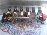
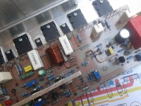
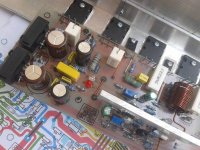
my first channel HoneyBadger ...
it glow! it stable and it sing very good
...it glow! it stable and it sing very good
Attachments
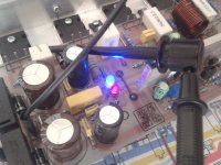
it glow!
it stable and
it sing very good
What more could anyone want from an amp!
Last edited:
my first channel HoneyBadger
it glow! it stable and it sing very good
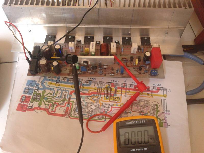
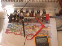
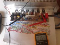
well done mas Naf, this is 0.0mV DC offset
very good building skill you have...
I'm waiting your complete amp...
If possible change mounting position on heatsink so that more solid & better heat transfer
Please tell me the sound review latter okay?
Regards
I think so it seas, Double sided design with 70um copper traces (twice the standard density)
http://www.diyaudio.com/store/boards.html
http://www.diyaudio.com/store/boards.html
Ersa,
Yes, thats the answer I was looking for, thanks. Zes at the top of board section
All our boards feature:
Double sided design with 70um copper traces (twice the standard density)
Gold plated through holes and vias
Flame resistant FR-4 military grade glass passivated substrate
Silkscreened part placement guides
Sent the same day*
Thanks Mark,
Yes, hope to build it this year, still have a number of unfinished projects that need attention and also need to do the PSU including transformers first for this "Badger" beast, the good thing is that I have some nice and big DIY casted heatsink for this one.
Tony
Yes, hope to build it this year, still have a number of unfinished projects that need attention and also need to do the PSU including transformers first for this "Badger" beast, the good thing is that I have some nice and big DIY casted heatsink for this one.
Tony
- Home
- Amplifiers
- Solid State
- diyAB Amp The "Honey Badger" build thread