
Ok. Things are a go: I'm getting 62.0 DCV +/- from both PSU channels.
Not sure what turned things around, but I might not have had a solid connection on one of my wires connected to the IEC.
Not sure what you are referring to regarding NTC resistors? I have used CL-60 inrush current limiters on all my First Watt builds. Are you suggesting I don't need to use them here? I understood they have a safety function.
Not sure what to conclude regarding the Mark Johnson soft-start. I'd like it in and working. But I will finally proceed with building a Badger amp board.
The CL-60 current limiters shouldn't be there. The soft-start board takes care of that. They will just cause the supply to sag under heavy load.
Class AB amps are different than class A. In a class A amp current draw is constant so the CL-60 would remain hot and have little resistance. There will be little current draw in a class AB amp under low volume and idle conditions which will allow the CL-60 resistors to cool down and raise their resistance so when the amplifier suddenly needs a quick burst of current the transformer will be current limited by the CL-60s. This is why the soft-start board bypasses all of the soft-start circuit with a relay, so it can't cause these issues.
Another thing different with Class A and AB amps is the constant current draw of a class A amplifier will negate the possibility of cross talk between channels. Class AB amplifier are more prone to cross talk because of the change in current draw with power output. It is usually well worth using a separate power supply for each channel. The sound stage is usually noticeably improved.
What value do you have for R19 and what component are you using for D3 ?My wife says she can hear a very low hum.
Is the hum coming out of your speaker or from the Amplifier itself?
Last edited:
Got it. I will remove the CL-60's. Thanks for the information on A vs AB. I was stuck in the Class A paradigm. I only removed the soft-start to try and isolate the source of the hum. I didn't achieve that so I will return the soft-start board.The CL-60 current limiters shouldn't be there. The soft-start board takes care of that. They will just cause the supply to sag under heavy load.
Class AB amps are different than class A. In a class A amp current draw is constant so the CL-60 would remain hot and have little resistance. There will be little current draw in a class AB amp under low volume and idle conditions which will allow the CL-60 resistors to cool down and raise their resistance so when the amplifier suddenly needs a quick burst of current the transformer will be current limited by the CL-60s. This is why the soft-start board bypasses all of the soft-start circuit with a relay, so it can't cause these issues.
Another thing different with Class A and AB amps is the constant current draw of a class A amplifier will negate the possibility of cross talk between channels. Class AB amplifier are more prone to cross talk because of the change in current draw with power output. It is usually well worth using a separate power supply for each channel. The sound stage is usually noticeably improved.
I would prefer to use separate power supplies, but I don't think I can fit them in and the two-amp boards as the heat sinks on the boards stick out too far. But I give that some more thought.
To-date all I have built and assembled is the PSU.What value do you have for R19 and what component are you using for D3 ?
Is the hum coming out of your speaker or from the Amplifier itself?
What transformer did you use?To-date all I have built and assembled is the PSU.
If it was an AnTek you may want to pot it. I needed to pot mine as you could hear the transformer humming due to what I'm assuming was the windings not been wounded tight enough.
Feel free to look at my Honey badger build album for the potting example.
Honey Badger Album
You may also want to search and read some of my other posts in this thread for some of the other mods and issues I found.
Does the transformer hum if you power it up directly with nothing connected to the outputs and sitting on a bench out of the chassis. If it's quiet that way, bolt it into the chassis and test again. Keep adding a single piece in the chain until you find what is causing it to start humming.
Potting is a last plan of attack. It's a messy process where you put it in a mold and pour epoxy over it. This shouldn't be necessary.
Potting is a last plan of attack. It's a messy process where you put it in a mold and pour epoxy over it. This shouldn't be necessary.
https://www.amazon.com.au/Smooth-Pourable-Urethane-Rubber-Elastomer/dp/B0874VPHNNI have a Antek 8445. Can you point me to where you acquired your pots?
This is what I used but they do make one that has an longer pot time. Which is what I'd recommend.
Hello Forum Members
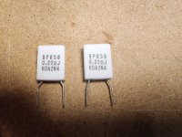
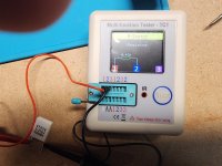
I am currently assembling the first of my two Honey Badger amplifier boards. As is good practice, I test every component that I'm able to test before placement. I'm currently placing the resistors R43-R48. I am using 0.22 ohm KOA Speer resistors with a tolerance of 5%. The first resistor I measured had a value of 0.44ohms. The second, as seen in the attached picture measured 0.43 ohms. Granted, I'm fairly new to this but do those readings seem a bit high?
Or, am I missing something so obvious that I will soon be learning something new about this craft? Thanks in advance for any feedback.
Attachments
If you don't have a meter that you trust for low resistance measurements you can always use ohms law to help you.
You could place your DMM in series with the resistor to measure current and then using a lab power supply output say, 600mV then measure the current through the resistor. For 0.22 ohms you should see about 2.73A
I = V ÷ R
This is approximately 1.6 watts so your 5 watt resistors can handle it.
You could place your DMM in series with the resistor to measure current and then using a lab power supply output say, 600mV then measure the current through the resistor. For 0.22 ohms you should see about 2.73A
I = V ÷ R
This is approximately 1.6 watts so your 5 watt resistors can handle it.
- Home
- Amplifiers
- Solid State
- diyAB Amp The "Honey Badger" build thread