Hi Aniket!thanks formula 22,
you made my amplifier even better, i would do the changes and mention the results later.
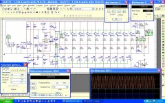
Earlier in the original circuit i set the bias to 25mA, output shows only 1mV, amplifier is dead quiet, no hum, no hiss.
what could be the ideal bias setting as you have included a trimpot in the schematic you updated.
Regards,
Aniket
BC139 for bias should be on the refrigerator (heatstink) with a 2N3773 or MJ15003 and the best with MJ15022 or MJ15024!!.
Quiescent current with 2k2 trimmer set at about 50mA.
Amplifier great works with these changes I have indicated in the schematics!!
2N3773 replacement with MJ15022 or MJ15024 and BD139 and BD140 replacment for MJE15032 and MJE15033!!
BD139 for bias remains.
Best regards and Cheers!

Last edited:
Thanks formula 22
i could do the changes you mentioned but genuine MJ15024 or MJ15003 are hard to find here. MJE15032/33 are sacred too, I would ask a friend who lives in Bangalore(Electronics City of India) if he could find there and make these mods.
I used TIP122/127 as drivers and they worked fine also.
Regards,
Aniket
@sakis- if you dont want posts originated from India then better not watch and post irrelevant to the subject or theme. I be a member of DIY to learn a lot and share little that i know.
Do you own DIY or DIY audio belongs to you. It seems a problem for you from where a member belongs. You should encorporate a filter or moderator not to allow people from India to be a member of DIY. I know that DIY is open for everyone no matter where you are from. I came here to learn, dont make this a bitter experience.
 whist I do not think that sakis was being malicious with his post, he has been given points for it. We are a multicultural forum and as per rule 9. discussion of ethnicity is not allowed. Posts from all races and nations are welcomed provided they follow the rules and the spirit of the forum.
i love statistics
I wonder if any moderator could actually "wash" through posts that originate from India where 9 out of 10 ask for more power
Is it DNA issue??? is it a local problem??? ( big amplifiers are too expensive ? ) who knows ....interesting though .....
I have received an penalty for my post from moderation and i apologize if this sounded like any insult to any forum member I only wanted to point the power issue ....i Have no racist issues with any other people .
I apologize again if after all what i wrote was wrong by all means .
Kind regards
sakis
Upgraded my amp
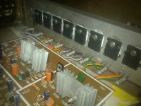
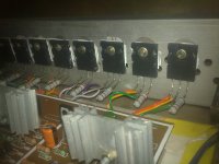
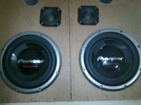
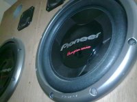
upgraded my amp using 2 pair of output devices (now 2SC5200/SA1943 earlier 2N3773), and the result is fantastic, more clean tight bass, crisp mids and highs, and even could feel more power. Attached are the pics, would upload updated schematic later.
@Sakis: Dear Sir, no need to apologize, I was also a bit harsh too, i wish you could help me to learn here, as i am a beginner and maybe less than half of your age")
upgraded my amp using 2 pair of output devices (now 2SC5200/SA1943 earlier 2N3773), and the result is fantastic, more clean tight bass, crisp mids and highs, and even could feel more power. Attached are the pics, would upload updated schematic later.
@Sakis: Dear Sir, no need to apologize, I was also a bit harsh too, i wish you could help me to learn here, as i am a beginner and maybe less than half of your age
Attachments
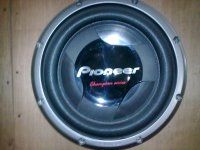
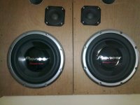
Our Indian subcontinent Members have been reading too many Car Audio magazines.
Here in India we use these speakers
Ahuja Sound Solutions

Add local decoupling both at the output devices and on the main supply rails.
Add degeneration resistors to the LTP.
Add a trimmer resistor to the 3k3 (lower one connected from Zener to LTP). This trimmer to set LTP in balance.
Add degeneration resistor to VAS
Add a third 3k3 in the supply to the Zener/LTP. The Zener can manage with a bit less than 9mA. Or try splitting the upper 3k3 into two off 2k2. Then add a smoothing cap between the 2k2 for extra filtering to the LTP tail. 10uF to 100uF would do.
If you feel you must run at lower bias currents in the output stage, then double the emitter resistors to 0r47. This will allow ~45mA of bias through each pair for near optimal ClassAB.
Last edited:
Hi Aniket .
Andrew's suggestion of a VAS emitter resistor is interesting ( I presume as that would degenerate the VAS ) . This can be up to 22 R as a rule of thumb . One amp I built recently was 16R . What you might hear is that the sound is punchier at 0R and softer as the resistance increases . A friend I built an amplifier for definitely preferred 0R . My quick guesstimate is that 4R7 will be about the trans-conductance point , l assuming gain to be about 100 for the BD139 . I suspect the critical values to be 0R 4R7 and 10 R . As your VAS current and voltage is low you might find a higher gain transistor for this application . I think 2N5551 would be OK ( often about g = 150 ) . Sanyo have excellent devices if you can get them . As you have 47 pF VAS cap I think it will be OK . The BD139 will be adding to that . You might start with 68 pF if trying something new as a precaution . Looking at the difficulties of changing a transistor a small emitter resistance seems an easy option . One other transistor is MPSA 42 . It's gain is lower so a higher value emitter resistor might be required . It has a good reputation and is cheap .
Technically speaking some say a VAS resistor is a bad idea as it reduces available negative feedback to correct crossover distortion ( as does the VAS cap ) . This is true . I find if a little is used and trans-conductance is reached or slightly exceeded then IM distrotion is lower . A trade between IM and crossover distortion is a nice game for the ears .
I like your bootstrap constant current source . Generally the 100 uF costs as much or more than a BD140 . How many have ever tried one ?
Study the Quad 303 output stage . It works very well . It could be adapted with extra output devices . The Quad can work with only 10 ma standing current . Rotel used 44mV @ 0R22 to set bias = 20 mA .
I think read up on bridging . It allows a stereo power amp to be converted into a high power mono unit . The advantages are compound . Not least no great investment to give it a try . If liked upgrading of heat sinks and power supplies comes next . A brief trial ( 10 minutes max ) should be possible before things get too hot . 4 ohms will need many output transistors .
Bridging Adapter For Power Amps
Bridging Adapter For Power Amps
"@djk how could i get more power out of this amp."
How much power?
What is it for?
Crown made the M600, M2000, MA10K all using the 2N3773.
The more outputs the more power (and a bigger power supply).
The M600 is a bridge amplifier.
The M2000 and MA10K are bridged bridge amplifiers (although the MA10K would only do 7KW continuous, 10KW on program material).
The M2000 was frequently used to generate a clean 120V/60hz for medical equipment.
The 3773 is a good output device for one that is limited by 140Vceo.
let's start with a +-65Vdc supply, that allows for a bit of overvoltage for the mains electricity supply. That supply will allow a maximum output of ~60Vpk into a suitable load.
60Vpk into 1r0 is equivalent to 1800W.
Now design and build those 3773 into a +-65Vdc balanced amplifier.
We can expect 3600W into a 2r0 load.
If sufficient capacity is built into the amplifier it could even be designed using a lot of skill to drive a 1r0 load to ~7kW.
Is that close enough to 10kW?
But, I would never recommend putting all my assets into a one amplifier PA duty. I would much rather have seven or eight 1kW amplifiers driving the speakers for my paying audience.
10kW with 2N3773 could be done by bridging 2 sets of grounded bridge amplifiers.........
I think that is why DJK quoted 10kW range.
Last edited:
- Status
- This old topic is closed. If you want to reopen this topic, contact a moderator using the "Report Post" button.
- Home
- Amplifiers
- Solid State
- Simple 100W power amp