I am on wrinting a new topic on TSSA BIGBT HP building we will continue further step overthere if you are aware for more clarity.
Marc
Where did you vanished Marc?


Story about subjective & objective measurement in Audio - all comments welcome
When I first built TSSA 1.6 one thing in particular struck me - even though my fetzilla has same gain & a Jfet input device TSSA 1.6 with BJT has less audible hiss !
This is a disturbing issue - in theory my amp should have less noise because of super low noise Jfet i/p device.
I already new the design needed some "housekeeping" because it sounded better without bypass caps - even with snubbers so I went to work to eliminate the spurious noise.
Day 1 added the snubberized bypass caps - sounded dreadful
Day 2 spent time searches out potential sources of noise and at the end of the day on the scope the noise was measurable less but when listening to audible hiss on the speakers it sounded just the same as before but now the music now sounded very very nice - conclusion: even if we can't hear difference in noise with our ears the scope tells us an accurate story
Day 3 Continue with search for sources of noise - try several things on right channel and compare to unmodified left channel on the scope. However at the end of the day I can see absolutely no difference of noise levels on the scope - over different frequencies ranges both channels look the same - BUT when I listen at end of day for audible hiss now the modified right hand channel is almost silent and the left channel is hissing away as usual. Conclusion: The scope does not tell an accurate story, we have to trust our ears !
Tomorrow I will modify left channel same as right and listen to music . . . . .
Last edited:
This is a disturbing issue - in theory my amp should have less noise because of super low noise Jfet i/p device.
I think it is the circuit, not the type of device used.
What is your JFET? JFET likes high current for low distortion, but high current with unsuitable JFET (Idss) will give high noise. Some favor 2SK170 because of its premium trans-conductance. I think there is some kind of dilemma in choosing the right JFET.
Minimal nvrtHz active part in amp level signals is not a primary issue. The feedback arrangement in SSA style is low impedance we must not forget and goes to emitters, so no contribution to a gate or a base of a classic long tailed pair. Random noise is uncorrelated so CMRR would not give as much a cancellation as in PSRR for 100Hz ripple.
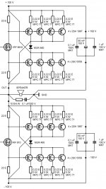
See the analogy now? Just parallel bipolar devices as many as you need same way as on the picture. Now all bipolars around one mosfet driver have to have the same current gain hFE (+/-5%)Hi LC,
Awesome output circuit you have posted - amazing!
I am not sure how to accurately connect it to the TSSA circuit you posted on page 16. Any hints for us novices?
Thanks.
P.S. IRF610/9610 mosfet drivers from your TSSA sch stays on positions as they are, so please ignore reversed mosfet positions on this pic because in Maximus it was completely different configuration of an output stage.
Attachments
Last edited:
When I first built TSSA 1.6 one thing in particular struck me - even though my fetzilla has same gain & a Jfet input device TSSA 1.6 with BJT has less audible hiss !
I was telling all the time how low noise level in this amp is. Low Z in every position is making the difference, probably lowering input Z would have similar noise result in Fetzila too.
Hi LC,
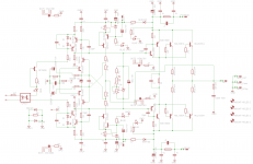
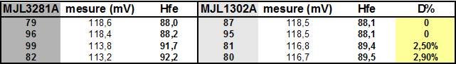
Since i am waiting tssa_bigbt_hp new filtering/smoothing caps for firste stage building, i have little to study new possibility for using my good matched pair of MJL3281 and MJL1302 (No BIGBT possibility since NPN/PNP matching is over 5%). I try to swap from BIGBT to BJT... (I say try....) base for moment on +-35Vdc
Marc
Attachments
Where did you vanished Marc?
In word format as you advice me to keep it for me until TSSA_BIGBT_HP is runnig. I have to purchase new smoothing/Filtering caps. Mine are coming from salvaged power supply and got some strange sounding behavier on other project.
Marc
Hi Marc, no problem if it is triple BJT output stage, VAS isolation from the output current would be great, so no other change required.
But as you remember we didn't pass the first task of setting CCS to correct current levels, or you already did it in the mean time?
Regards Andrej
But as you remember we didn't pass the first task of setting CCS to correct current levels, or you already did it in the mean time?
Regards Andrej
Thanks to all for your responses - actually now after the measures I took the noise in the modified channel is very low - almost inaudible with my ear actually touching the face plate of the tweeter and CLG of 23 - so for now I am satisfied with this.
I am looking forward, when I have converted the other channel, to make another comparison of noise & music between TSSA 1.6 & my amp - but already both sound very good.
I think I will have to stop calling my amp Fetzilla to avoid confusion with Hugh's design from which it differs in several ways and also because it now it is not exclusively made with fets so from now on I will call it Simple S.E.A.
I also look forward to make a comparison with SSA ASAP but first I have to build it !
I think TSSA, SSA & Simple SEA are like 1st cousins and I am grateful to Andrej & Sonny because I set you very high standard in design that inspires me to understand and improve my own design efforts.
Last edited:
Hi Marc, no problem if it is triple BJT output stage, VAS isolation from the output current would be great, so no other change required.
But as you remember we didn't pass the first task of setting CCS to correct current levels, or you already did it in the mean time?
Regards Andrej
HI LC that's just "paper job" or "computer job"....i explain why i have not proceed to TSSA_BIGBT first test. I do not trust enough my actual smoothing/filtering caps and wait on some new. The soft start/speaker protection board is ok and functionnel so LTP327 can be feed.
Can you developpe :
VAS isolation from the output current would be great
I choose your TSSA shématic beacause you provide the table with Vrail conversion value. I just have interrogation about value toward Vrail amout on the resistor feeding Driver (MJE15030/15031)base : 100R in my schematic.
Marc
VAS isolation from the output current means, that ratio (current gain) between output current level (speaker load current) and VAS loading current or base current (Ib) to input BJT of the triple output stage is enormous. Let say for 10 A load current, VAS loading current would be only few mA, ratio more than 1000, current isolation more than 60 dB. Clear now?
100 ohm sets too low bias current for driver (second BJT in triple) it should be 22 ohm for app. 30 mA driver's bias.
100 ohm sets too low bias current for driver (second BJT in triple) it should be 22 ohm for app. 30 mA driver's bias.
i have little to study new possibility for using my good matched pair of MJL3281 and MJL1302 (No BIGBT possibility since NPN/PNP matching is over 5%)
Marc
Not 100% right i look foward and think i found one more new BIGBT possibility by new project devices repartition
Marc
Attachments
See the analogy now? Just parallel bipolar devices as many as you need same way as on the picture. Now all bipolars around one mosfet driver have to have the same current gain hFE (+/-5%)
P.S. IRF610/9610 mosfet drivers from your TSSA sch stays on positions as they are, so please ignore reversed mosfet positions on this pic because in Maximus it was completely different configuration of an output stage.
LC thanks - I get it.
The extra components on the first drawing confused me.
Now to order parts from Mouser.
Not 100% right i look foward and think i found one more new BIGBT possibility by new project devices repartition
Marc
Yes, these BJTs are more than adequate for BIGBT application.

- Home
- Amplifiers
- Solid State
- TSSA - The Simplest Symmetrical Amplifier