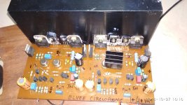
I have assembled the circlophone this Evening,I used project 16's layout. I will upload a photo in due course.
As per Vijay's request, here's a pic of his Circlophone build which he forwarded to me earlier. We auditioned it yesterday with my setup, and it is indeed exemplary as claimed.
Just minor observations:
1) It needs about 5 to 10 minutes of warm-up for optimal sonics.
2) It does better with my modified 2-way Lyrita Horn Grande with 3rd-order Elliptic XO for the woofer and 1st-order for the mid/high, than with an unmodified Technics SB-CR77 3-way. Both have 12" woofers and vented cabinets, but the Technics sounded a bit bright in the upper mids. The Circlophone/Lyrita combo was perfect across the board, and the amplifier almost completely dropped out of the picture, adding no coloration or anything perceptible to the sonics, especially when listening to Indian vocals (that's huge in the local context, because almost everything here has vocals). It has brilliant imaging and instrument separation as well.
3) We tried and then removed a opamp-based pre-amp from the audio chain - the pre- was too veiled and coloured for such a transparent setup.
4) Input coupling caps are Sanyo CZ 4.7uF/50V electrolytics, which measure great on DF (~0.5%, almost on par with Rubycon BG STD). After listening to the audible sonics, I can't really find a reason to substitute these with film caps - I'll reserve the experimentation for future builds if needed.
5) Outputs were warm to the touch, but not excessively so.
6) VAS uses BEL 2N3501, slightly more expensive than BF469/470/869/870 locally - will give the latter a try in future builds. Sanyo 2sc3953 may also be workable - a variety of NOS Chroma transistors are locally available.
7) Power Schottkys are MBR745, which are not always easy to source locally. We'll look for commodity substitutes in due course - there are some inexpensive 5A axial-lead Schottkys around.
To reiterate, this is an exceptional topology with transparent sonics that requires no tweaking or alignment, at a slightly higher BoM than a good gainclone. Highly recommended.
Attachments
50V supplies translate into ~130W/8ohm, which is a bit much for a single pair of regular OP transistors.Have anybody built circlophone with higher rail voltage, say +/- 50V?
What transistors to use?
Suitable transistors do exist, up to 350W Pd max (MGsomething, IIRC) but they are not very common.
It would of course be possible to parallel a number of OP devices, but this would require emitter resistors for balancing, which is not ideal with this topology (perfectly doable though, using Onsemi MJL series for example).
IIRC, some members have explored higher power levels like ~100W, it must be somewhere in the main circlophone thread.
I have described a dedicated discrete buffer for the circlophone, it is also somewhere in the main circlo thread....3) We tried and then removed a opamp-based pre-amp from the audio chain - the pre- was too veiled and coloured for such a transparent setup.
With a bit of patience and determination, it should be possible to dig it out
50V supplies translate into ~130W/8ohm, which is a bit much for a single pair of regular OP transistors.
Suitable transistors do exist, up to 350W Pd max (MGsomething, IIRC) but they are not very common.
It would of course be possible to parallel a number of OP devices, but this would require emitter resistors for balancing, which is not ideal with this topology (perfectly doable though, using Onsemi MJL series for example).
IIRC, some members have explored higher power levels like ~100W, it must be somewhere in the main circlophone thread.
Thanks Elvee!
I need 100W amp, but I happen to have PSU +/- 50V.
1 pair of MJ21194 should be enough and safe for that..
I guess Piersma's Inverted Jfet can do +/- 50V, so that's one option.
But 2SK170 jfets are difficult to get, and also expensive...
Just a thought - with music signal (not a square or sinus wave), is it actually possible to extract REAL 150W from 2 transistors, with 50V rails?
An update: After reading back the thread again, I found that Elvee, used 180pf for C12 for 2n3055. In my build, i had installed 470 pf and my output transistors are tip3055.I removed 470 pf and soldered 220pf, and the results are stunning. The sound stage has an exceptional depth and vocals were terrific. Instruments had the so called "presence"...I never had an idea that this cap will have such tremendous influence on sonics. In short, anybody who uses 3055, please see to that c12 is 180 pf or 220pf.Circlophone has revealed its true potential and I am very much excited.
Certainly not 150W: the theoretical max possible is 156.25W, and although the C is rather efficient, it still needs a little margin to operate.Thanks Elvee!
I need 100W amp, but I happen to have PSU +/- 50V.
1 pair of MJ21194 should be enough and safe for that..
I guess Piersma's Inverted Jfet can do +/- 50V, so that's one option.
But 2SK170 jfets are difficult to get, and also expensive...
Just a thought - with music signal (not a square or sinus wave), is it actually possible to extract REAL 150W from 2 transistors, with 50V rails?
Thus, the actual max would be something like 135~140W/8ohm.
Using a single pair to achieve that is certainly possible, but if your transistors are weak on Pd max and SOA and your speaker is a difficult one, it won't last long before the magic smoke escapes.....
In principle, a cascode should be better, but in practice, no one has been able to tell the difference, neither in listening tests, nor in measurements...Also, one more question.
Actually two:
1) should I build version with cascode, or original version with zeners ?
The cascode does however bring a totally unrelated advantage: it makes the amp insensitive to the supply voltage, which could be advantageous if you need to swap boards or supplies
Same remarks as above2) is it worth to replace R21 with more advanced current source that was described later on? Have anyone actually tried it?
I think Terranigma tried one (or both) options
Have anybody built circlophone with higher rail voltage, say +/- 50V?
What transistors to use?
I did with +-50V using vertical mosfets at output. You probably even go beyond 100W with well matched mosfets connected in parallel. You may find the schematic on main thread but I don't remember the link. The good thing about hexfet version is, it doesn't need driver transistors and using same gender mosfets that brings near optimal results for this type of devices. Circlophone's considerably high bias current gives a cure for linearity problems of vertical mosfets.
I think Terranigma tried one (or both) options
I build small vertically mounted pcb that fits on resistor (R21) footprint. It was a single transistor constant current circuit designed by you. Also somewhere in main thread.
Last edited:
Thanks Terranigma,
I found your posts regarding hexfet circlophone,
but I'm unable to find the schematic.
I only see your PCB that supports hexfets..
From your posts and from the pcb, it seems like the schematic is pretty much the same, with one hexfet replacing
a driver and an output transistor, just like for darlingtons, right?
I did with +-50V using vertical mosfets at output. You probably even go beyond 100W with well matched mosfets connected in parallel. You may find the schematic on main thread but I don't remember the link. The good thing about hexfet version is, it doesn't need driver transistors and using same gender mosfets that brings near optimal results for this type of devices. Circlophone's considerably high bias current gives a cure for linearity problems of vertical mosfets.
Last edited:
♫♪ My little cheap Circlophone© ♫♪ ==Post No 62 of the original thread.
♫♪ My little cheap Circlophone© ♫♪ -- Post 1172 of original thread.
♫♪ My little cheap Circlophone© ♫♪
♫♪ My little cheap Circlophone© ♫♪ -- Post 1172 of original thread.
♫♪ My little cheap Circlophone© ♫♪
Thanks!
♫♪ My little cheap Circlophone© ♫♪ ==Post No 62 of the original thread.
♫♪ My little cheap Circlophone© ♫♪ -- Post 1172 of original thread.
♫♪ My little cheap Circlophone© ♫♪
hello to everyone, after some small problem I managed to make everything work, now with my dear friend we wanted to change something like to replace the two zener with a BJT.
I saw that the original main scheme
♫♪ My little cheap Circlophone© ♫♪ - diyAudio
and his simulator file are very different.
http://www.diyaudio.com/forums/atta...-little-cheap-circlophone-circlophone.asc.txt
why?
I saw that the original main scheme
♫♪ My little cheap Circlophone© ♫♪ - diyAudio
and his simulator file are very different.
http://www.diyaudio.com/forums/atta...-little-cheap-circlophone-circlophone.asc.txt
why?

Finally ordered bc556b 2sa1930/2sc5171 from electronics salon since i wasnt able to use diyaudiocart, and the other parts will be ordered from mouser. Guess i´m gonna use alexmm design, modified for 2sc vas.
Anyway messing around in mouser a "new product" toshiba bjt appears in stock and they seem to be a good option for driver and vas since they have acceptable cob: TTC004B (npn 12pf) and TTA004B (pnp 17 pf).
https://www.mouser.de/datasheet/2/408/TTC004B_datasheet_en_20180223-1102342.pdf
https://www.mouser.de/datasheet/2/408/TTA004B_datasheet_en_20170109-1102732.pdf
those are the datasheets. Do you think they may work? has anyone tried them? Their hfe range doesn't seem wide either from 140 to 280...
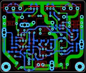
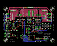
Circlophone using TTC004B
I successfully used TTC004B as VAS transistors on my circlophone. I currently have only one channel working on a temporary heatsink. Testing so far has been rather minimal. Both channels will go into a permanent enclosure next month. PCB is my design: the only significant differences from most other circlophone PCBs are changing the VAS transistors to TO-126, and moving the KSA1220 drivers and MJL21194 outputs to better support mounting the PCB on the heatsink.
Finally ordered bc556b 2sa1930/2sc5171 from electronics salon since i wasnt able to use diyaudiocart, and the other parts will be ordered from mouser. Guess i´m gonna use alexmm design, modified for 2sc vas.
Anyway messing around in mouser a "new product" toshiba bjt appears in stock and they seem to be a good option for driver and vas since they have acceptable cob: TTC004B (npn 12pf) and TTA004B (pnp 17 pf).
https://www.mouser.de/datasheet/2/408/TTC004B_datasheet_en_20180223-1102342.pdf
https://www.mouser.de/datasheet/2/408/TTA004B_datasheet_en_20170109-1102732.pdf
those are the datasheets. Do you think they may work? has anyone tried them? Their hfe range doesn't seem wide either from 140 to 280...
I successfully used TTC004B as VAS transistors on my circlophone. I currently have only one channel working on a temporary heatsink. Testing so far has been rather minimal. Both channels will go into a permanent enclosure next month. PCB is my design: the only significant differences from most other circlophone PCBs are changing the VAS transistors to TO-126, and moving the KSA1220 drivers and MJL21194 outputs to better support mounting the PCB on the heatsink.
Attachments
Greaat, that´s really good news! I now nothing about pcb design but your board seems really easy to heatsink with only four little 2nd hand HS (actually what i got ;D). I´m guessing someone would be able to switch between 2sc5171 and TTC004B by simply fliping it 180° (since one pinout is EBC and the other CBE?). I may be interested in the future if you have any spare board.
congratulations for your build !
Regards
congratulations for your build !
Regards
Greaat, that´s really good news! I now nothing about pcb design but your board seems really easy to heatsink with only four little 2nd hand HS (actually what i got ;D). I´m guessing someone would be able to switch between 2sc5171 and TTC004B by simply fliping it 180° (since one pinout is EBC and the other CBE?). I may be interested in the future if you have any spare board.
congratulations for your build !
Regards
The four transistors to be heatsinked require M3 screws. Drilling and tapping your heatsink to take M3 screws is not that hard and is a good skill to learn. The PCB also has four holes for proper mounting but you probably can just use the four transistors to hold the PCB in place.
TTC004B and 2sc5171 seem very similar except the pinout is ECB vs BCE. Fortunately, flipping the 2s5171 180° is all that is required.
I do have a couple for spare boards, and can make the gerbers available to anyone who wants to have their own boards manufactured.
Surprisingly, the link worked. ♫♪ My little cheap Circlophone© ♫♪ aaaaand go to post#637...I have described a dedicated discrete buffer for the circlophone, it is also somewhere in the main circlo thread.... With a bit of patience and determination, it should be possible to dig it out
- Home
- Amplifiers
- Solid State
- Building Elvee's Circlophone: Documentation, Parts, Accessories, & beginner friendly