Hello all. I considered putting this in the SPICE forum but I put it here because I knew a lot of people might not see it, and it does pertain to solid-state amplifiers loosely. If this is not appropriate please move it, mods.
I was not satisfied with the model quality of the 5200/1943 transistors. The best models I could find were the Fairchild models for the FJP5200/1943. But it is obvious that parameters for these came from a single model and then the differences confabulated; just compare them and you'll see the numbers are cooked. I don't think a machine did this.
Even so I based my new models on these. I adjusted for correct Vbe, reasonable Hfe curve, correct device capacitances (I actually measured the capacitances). I was not able to do Vce saturation, and I don't know how accurate it is. And like all models, no quasi-saturation, so be sure to know this and know why it's important.
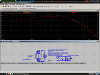
Ft vs Ic should be reasonable to 1A, the old models didn't have large enough Cje so they were way too fast at low currents.
These models are approximate, but more realistic than any other model I think, and they will be what I use from now on. They will not be as accurate perhaps as those from Cordel or AndyC, but they are good enough for me, and SPICE is an approximation anyway.
Hope this helps.
.MODEL 2SC5200_k npn IS=300f BF=100 NF=1 BR=8.025 NR=1.0 ISE=200p IKF=18 NE=2.0 ISC=2.01764E-10 NC=1.5 VAF=400 VAR=100 IKR=1.39087 RB=1.1 RBM=0.00011 IRB=1.51189E-6 RE=0.0032 RC=0.0183 CJE=6.1n VJE=0.711 MJE=0.304 FC=0.5 CJC=380p VJC=0.84 MJC=0.25 TF=5n TR=3.342E-7 XTB=1.72 EG=0.78 XTI=3
.MODEL 2SA1943_k pnp IS=650f BF=100 NF=1 BR=8.805 NR=1.0 ISE=10p IKF=15 NE=2.0 ISC=2.01764E-10 NC=1.5 VAF=600 VAR=100 IKR=1.39087 RB=1.1 RBM=0.00011 IRB=1.51189E-9 RE=0.0061 RC=0.0103 CJE=5.26n VJE=0.711 MJE=0.304 FC=0.5 CJC=750p VJC=0.84 MJC=0.25 TF=5n TR=3.342E-7 XTB=2.28 EG=0.81 XTI=3
I was not satisfied with the model quality of the 5200/1943 transistors. The best models I could find were the Fairchild models for the FJP5200/1943. But it is obvious that parameters for these came from a single model and then the differences confabulated; just compare them and you'll see the numbers are cooked. I don't think a machine did this.
Even so I based my new models on these. I adjusted for correct Vbe, reasonable Hfe curve, correct device capacitances (I actually measured the capacitances). I was not able to do Vce saturation, and I don't know how accurate it is. And like all models, no quasi-saturation, so be sure to know this and know why it's important.
Ft vs Ic should be reasonable to 1A, the old models didn't have large enough Cje so they were way too fast at low currents.
These models are approximate, but more realistic than any other model I think, and they will be what I use from now on. They will not be as accurate perhaps as those from Cordel or AndyC, but they are good enough for me, and SPICE is an approximation anyway.
Hope this helps.
.MODEL 2SC5200_k npn IS=300f BF=100 NF=1 BR=8.025 NR=1.0 ISE=200p IKF=18 NE=2.0 ISC=2.01764E-10 NC=1.5 VAF=400 VAR=100 IKR=1.39087 RB=1.1 RBM=0.00011 IRB=1.51189E-6 RE=0.0032 RC=0.0183 CJE=6.1n VJE=0.711 MJE=0.304 FC=0.5 CJC=380p VJC=0.84 MJC=0.25 TF=5n TR=3.342E-7 XTB=1.72 EG=0.78 XTI=3
.MODEL 2SA1943_k pnp IS=650f BF=100 NF=1 BR=8.805 NR=1.0 ISE=10p IKF=15 NE=2.0 ISC=2.01764E-10 NC=1.5 VAF=600 VAR=100 IKR=1.39087 RB=1.1 RBM=0.00011 IRB=1.51189E-9 RE=0.0061 RC=0.0103 CJE=5.26n VJE=0.711 MJE=0.304 FC=0.5 CJC=750p VJC=0.84 MJC=0.25 TF=5n TR=3.342E-7 XTB=2.28 EG=0.81 XTI=3
Attachments
Last edited:
PS: The more you do modeling, the easier it gets. I did this in a few hours. It shouldn't be hard for anyone to get mostly-realistic models based on the datasheet if they take some time to get familiar with the process. I did this all by hand, no spreadsheets (maybe I should've though)
I used my signal generator and scope, with a 1k resistor. I applied a 7.5V bias to the collector to measure the capacitance, and subtracted the capacitance of the scope and probe. I measured the Cje with 0V bias, but the measurement was only about 18mV so I don't think the junction could have been conducting.
Someone requested the SPICE file in my screenshot, so I'll attach it here. Also attached is the blank test fixture schematic that I used, since the other one has some impromptu junk on it I used to adjust Cje.
Attachments
- Status
- This old topic is closed. If you want to reopen this topic, contact a moderator using the "Report Post" button.