Noise
Hi David,
I think it's feasible to get as low as 2nV/rt Hz if you lower the source resistors to 50 Ohms. But keep in mind that it also has an effect on ULGF. So you have to adjust the compensation stuff as well.
Regarding the noise of the current mirror degen. resistors, not much is gained if you make them much larger than 22 Ohms. In the extreme case of 1kOhms, the noise will drop by about 0.17 nV/ rt Hz (depending on the amount of noise from other sources, of course).
BTW, what about the noise of your pre-amp and the volume pot?
Cheers,
E.
One ensures adequate, but not excessive, system gain for each of the alternative (frequency) channels.what about the noise of your pre-amp and the volume pot?
TIS with simple BJT output THD Sim
Hello Edmond
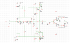
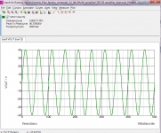
I did some some THD simulations with circuit attached and into 8R 20Khz I achieved 0.002% THD at 80V PP.
I must confess this seems to me a little bit high with the TIS input stage. Have you done sims with a simple output stage what sort of results do you get .
Regards
Arthur
Hello Edmond
I did some some THD simulations with circuit attached and into 8R 20Khz I achieved 0.002% THD at 80V PP.
I must confess this seems to me a little bit high with the TIS input stage. Have you done sims with a simple output stage what sort of results do you get .
Regards
Arthur
Attachments
THD20k = 20ppm
Hi Arthur,
I'm not surprised, as I got similar results with a BJT OPS.
This TIS is especially designed for the AB2 OPS with MOSFETs.
edit: Remember, compared to more conventional amps, your circuit has one gain stage less, i.e the VAS.
Cheers,
E.
Hi Arthur,
I'm not surprised, as I got similar results with a BJT OPS.
This TIS is especially designed for the AB2 OPS with MOSFETs.
edit: Remember, compared to more conventional amps, your circuit has one gain stage less, i.e the VAS.
Cheers,
E.
Last edited:
2 nV/rt Hz is acceptable - just! If we have the distortion down to -160dB we may as well make the noise at least inaudible!Hi David,
I think it's feasible to get as low as 2nV/rt Hz if you lower the source resistors to 50 Ohms. But keep in mind that it also has an effect on ULGF. So you have to adjust the compensation stuff as well.
Regarding the noise of the current mirror degen. resistors, not much is gained if you make them much larger than 22 Ohms. In the extreme case of 1kOhms, the noise will drop by about 0.17 nV/ rt Hz (depending on the amount of noise from other sources, of course).
BTW, what about the noise of your pre-amp and the volume pot?
Cheers,
E.
If I worked it correctly, the best way to analyse the CM resistor noise is not to consider the resistance itself but the voltage across it. Sort of like "quiescent current" in the OPS is better is expressed as the Oliver criterium of so many millivolts on the emitter resistors. Ideally one wants a couple of volts across the CM resistors to make any further improvements of CM noise trivial.
So we know what impact on output volts.
But then, as you point out, there's the other stuff. The pre-amp is the _next_ project! Volume control by manipulation of the feedback loop perhaps. Need to study this stuff too.
Thanks
David
Last edited:
Thanks, David.
I'm glad we share the same 'instinct'
BTW, 20mA is a lot of current for an IPS; trannies will get pretty hot.
Cheers,
E.
20 mA would be a bit hot without an IPS cascode, but since your circuit has one I may as well use the lower drop across the diff. pair. The extra current in the Baxandall pairs is about optimum to maximize their Ft and that also seems the correct direction.
In answer to your actual question- No one has mentioned the AD797. Is this not a bit similar? I have only ever seen simplified circuits of that op-amp and they had no Baxandall pairs but it has plenty of open loop so some of the schematic "transistors" are perhaps physical pairs.
This is a repost of an earlier attempt that seems to have failed. Sorry if a bit late.
David
Last edited:
Hello Edmond
I did some some THD simulations with circuit attached and into 8R 20Khz I achieved 0.002% THD at 80V PP.
I must confess this seems to me a little bit high with the TIS input stage. Have you done sims with a simple output stage what sort of results do you get .
Regards
Arthur
Quite apart from possible benefits to the diff. pair, would it help to increase the Baxandall pair current? Will sim this when I can but it seems this may increase its ability to drive the OPS?
Best Wishes
David
Hello Edmond
I did some some THD simulations with circuit attached and into 8R 20Khz I achieved 0.002% THD at 80V PP.
[...]
Regards
Arthur
Hi Arthur,
Perhaps you get better results if you connect the compensation cap(s) to the emitters of the pre-drivers. See fig.2 on my website.
Cheers,
E.
AD797
Hi David,
Although I wasn't inspired by the AD797, it just happened that basically both circuits share indeed the same philosophy: only two stages with high gain and folded cascodes. On the other hand, there are also big differences: apart from Baxandall super pairs, no floating current mirror and a totally different frequency compensation.
>I have only ever seen simplified circuits of that op-amp
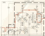
See below for more details of the AD797. Regrettably I don't have accurate models of the transistors.
Cheers,
E.
[...]
In answer to your actual question- No one has mentioned the AD797. Is this not a bit similar? I have only ever seen simplified circuits of that op-amp and they had no Baxandall pairs but it has plenty of open loop so some of the schematic "transistors" are perhaps physical pairs.
[...]
David
Hi David,
Although I wasn't inspired by the AD797, it just happened that basically both circuits share indeed the same philosophy: only two stages with high gain and folded cascodes. On the other hand, there are also big differences: apart from Baxandall super pairs, no floating current mirror and a totally different frequency compensation.
>I have only ever seen simplified circuits of that op-amp
See below for more details of the AD797. Regrettably I don't have accurate models of the transistors.
Cheers,
E.
Attachments
Hi Edmond
Congratulate you with inventing and introducing relatively simple circuit with superb linearity.
I think it can become a standard for the years.
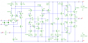
But why do you call it “transimpedance”? Common base stage is not transimpedance, even if you use a super pair instead of a single transistor, and the whole circuit is definitely transconductance (98 mA/V).
IMHO, it can be called something like “an LTP loaded with current mirror fully cascoded with super pair in a complementary configuration”, where “fully cascoded” means your combination of conventional and folded cascoding, that I’ve never seen before.
This long name is inconvenient, but shows the way to define what each component of the whole circuit gives to excellent performance.
1.We can exclude “complementary configuration” by connecting bases of Q1 and Q6 to the ground (I mean Fig.1 on http://home.tiscali.nl/data.odyssey/Super_TIS.html).
2.We can exclude “fully cascoded” by connecting collectors of Q5 and Q6 to +50v and -50v.
3.We can exclude “super pair” by connecting bases of Q10 and Q11 to V4 and V5 (1.5v).
4.We can make combinations of 1,2,3, each time measuring THD20k.
Would you like to do this?
With best wishes – Mir
PS. A short name may be “Stewart Audio Front End” (SAFE) – like “Baxandall Super Pair”. S may also mean “super”.
Congratulate you with inventing and introducing relatively simple circuit with superb linearity.
I think it can become a standard for the years.
But why do you call it “transimpedance”? Common base stage is not transimpedance, even if you use a super pair instead of a single transistor, and the whole circuit is definitely transconductance (98 mA/V).
IMHO, it can be called something like “an LTP loaded with current mirror fully cascoded with super pair in a complementary configuration”, where “fully cascoded” means your combination of conventional and folded cascoding, that I’ve never seen before.
This long name is inconvenient, but shows the way to define what each component of the whole circuit gives to excellent performance.
1.We can exclude “complementary configuration” by connecting bases of Q1 and Q6 to the ground (I mean Fig.1 on http://home.tiscali.nl/data.odyssey/Super_TIS.html).
2.We can exclude “fully cascoded” by connecting collectors of Q5 and Q6 to +50v and -50v.
3.We can exclude “super pair” by connecting bases of Q10 and Q11 to V4 and V5 (1.5v).
4.We can make combinations of 1,2,3, each time measuring THD20k.
Would you like to do this?
With best wishes – Mir
PS. A short name may be “Stewart Audio Front End” (SAFE) – like “Baxandall Super Pair”. S may also mean “super”.
suitable name
Hi Mir,
Thank you!
And perhaps even the end of the ubiquitous (and boring!) blameless topology.
Regarding Q7...Q12 in isolation, you are perfectly right. It is a CCCS with a (current) gain of just 1.
On the other hand, since the output of this stage is tied to a (well defined) impedance, the final output signal takes the form of a voltage source (well, at least, that's the intention). This is even more true for the 2nd figure (the emitters of Q19/20). So, in this respect, we might call it a TIS.
Please, look here for a further discussion.
Sure, but not now. Perhaps next week. But first I have to update my website with a comparison between OMC vs TPC vs TMC.
Well, that's too much honor. Besides, we mustn't forget the input from:
Dimitri Danyuk, "On the Optimization of Enhanced Cascode", AES paper, October 2008.
So, 'BDS front end'?
Cheers,
E.
Hi Edmond
Congratulate you with inventing and introducing relatively simple circuit with superb linearity.
Hi Mir,
Thank you!
I think it can become a standard for the years.
And perhaps even the end of the ubiquitous (and boring!) blameless topology.
But why do you call it “transimpedance”? Common base stage is not transimpedance, even if you use a super pair instead of a single transistor, and the whole circuit is definitely transconductance (98 mA/V).
Regarding Q7...Q12 in isolation, you are perfectly right. It is a CCCS with a (current) gain of just 1.
On the other hand, since the output of this stage is tied to a (well defined) impedance, the final output signal takes the form of a voltage source (well, at least, that's the intention). This is even more true for the 2nd figure (the emitters of Q19/20). So, in this respect, we might call it a TIS.
Please, look here for a further discussion.
IMHO, it can be called something like “an LTP loaded with current mirror fully cascoded with super pair in a complementary configuration”, where “fully cascoded” means your combination of conventional and folded cascoding, that I’ve never seen before.
This long name is inconvenient, but shows the way to define what each component of the whole circuit gives to excellent performance.
1.We can exclude “complementary configuration” by connecting bases of Q1 and Q6 to the ground (I mean Fig.1 on http://home.tiscali.nl/data.odyssey/Super_TIS.html).
2.We can exclude “fully cascoded” by connecting collectors of Q5 and Q6 to +50v and -50v.
3.We can exclude “super pair” by connecting bases of Q10 and Q11 to V4 and V5 (1.5v).
4.We can make combinations of 1,2,3, each time measuring THD20k.
Would you like to do this?
Sure, but not now. Perhaps next week. But first I have to update my website with a comparison between OMC vs TPC vs TMC.
With best wishes – Mir
PS. A short name may be “Stewart Audio Front End” (SAFE) – like “Baxandall Super Pair”. S may also mean “super”.
Well, that's too much honor. Besides, we mustn't forget the input from:
Dimitri Danyuk, "On the Optimization of Enhanced Cascode", AES paper, October 2008.
So, 'BDS front end'?
Cheers,
E.
Hi Edmond,
Nice circuit!
Thank you Steven.
I think I have seen the Baxandall super pair only be used in commercial amplifiers from Yamaha, such as the MX2000, the XP1000/2500/3500, the XS250/350...
Steven
You're right, these amps do contain Baxandall super pairs. However, in this case they are used differently: as a TIS (or a VAS or CCCS if you like) which also provide current gain. In case of the "Super TIS", the Baxandall super pairs are use as cascode, which provides no current gain (just 1x). Here, it's the next stage (pre-driver) that provides the current gain.
BTW, I get the impression that among the established audio guru's nobody realizes/recognizes the far reaching implications of moving the gain to the next stage.
Cheers,
E.
BTW, I get the impression that among the established audio guru's nobody realizes/recognizes the far reaching implications of moving the gain to the next stage.
Probably not gonna happen until people are gonna bite the bullet and try to build this thing.
BTW, I've loaded the full TIS plus the output stage (per your web site "Super TIS integrated with an Auto Bias-II Output Stage") in the simulator and had troubles with the stability, for the original TMC compensation values. The global loop is though stable, so it must be some sort of local (Miller?) stability issue (for the moment, I don't have the time to get more in depth). 3x larger TMC caps were required to stabilize the thing under all circumstances - but then the THD20 was "only" 20ppm @4ohm, just before clipping (yes, I know, Cadence sucks, models are different, MC rules, I am ignorant, etc...). Still impressive, but I wouldn't hold my breath to see this working properly, outside the simulator...
And speaking about performances, I wonder if the sheer complexity is worth even a x10 improvement over an optimal Blameless implementation. Is it worth the effort (and cost) to improve from 20ppm to, say, 2 ppm?
There are a few good reasons why TMC "shines" in this configuration, compared to TPC. It's though not an apple to apple comparison here, more perhaps later.
Last edited:
Walter,
There are many loops, not just global and Miller, but also the differential and common mode loops of the AB2 circuit and the loop of the O/P current limiter. All of these loops have to verified. That means a lot of work.
But first, what were the symptoms of the instability?
>Is it worth the effort (and cost) to improve from 20ppm to, say, 2 ppm?
I can't answer that question. The only thing I can say is that, when squeezing out the last ppm's of distortion, you will inevitably be confronted with the law of "diminishing returns".
Cheers,
E.
Probably not gonna happen until people are gonna bite the bullet and try to build this thing.
[...]
Come on. You don't have to build that thing in order to prove that the super TIS solves two known issues at once that plagued a fully complementary front end. These issues are (or better: were):
1. An ill defined quiescent current of the VASes (see the Randy Slone amp)
2. The issue of the so called 'fighting' VASes (caused by unequal gain of top and bottom VAS and/or unequal compensation caps).
Cheers,
E.
That means a lot of work.
But first, what were the symptoms of the instability?
Stable at zero input. As soon as a small signal (say, 100mV@20KHz) is added to the input, output goes into oscillation @ about 1MHz.
Come on. You don't have to build that thing in order to prove that the super TIS solves two known issues at once that plagued a fully complementary front end. These issues are (or better: were):
1. An ill defined quiescent current of the VASes (see the Randy Slone amp)
2. The issue of the so called 'fighting' VASes (caused by unequal gain of top and bottom VAS and/or unequal compensation caps).
You answered your own question: nobody cares about squeezing the last ppm out of an audio amp. There are other performance criteria, like "fashionable design" ["zero global feedback", SS and tube mixtures, other buzzword based BS]. Build it, then start BSing about "the wonderful sound of TIS", and with lots of luck you may have a chance to promote the concept.
Different story in IC design for ultra low distortion (e.g. required in DSL drivers, 'cause any drop of noise or distortion maps to extra bandwidth). But then in IC designs you don't have to use TIS to squeeze the last drop of performance. Free matching of devices makes implementing non-gm doubling complementary stages (and also avoiding the issues you are mentioning above) very easy. Not to mention the availability of essentially free transistors with Ft in the GHz range, allowing unity loop gains of hundreds of MHz.
You're right, these amps do contain Baxandall super pairs. However, in this case they are used differently: as a TIS (or a VAS or CCCS if you like) which also provide current gain. In case of the "Super TIS", the Baxandall super pairs are use as cascode, which provides no current gain (just 1x). Here, it's the next stage (pre-driver) that provides the current gain.
Hi Edmond,
I know Yamaha uses them in a completely different (traditional) way. It was just because Baxandall pairs are almost never used in commercial designs and some discussion arose about stability issues, that I wanted to show these applications of the Baxandall pair.
BTW Already in 2004 these stability issues were discussed on this forum, both as TIS (VAS) and as cascode stage: http://www.diyaudio.com/forums/solid-state/25172-baxandall-super-pair.html#post293504. But going through that thread I just saw that also Yamaha's use of it was already mentioned.
I've never seen your use of the Baxandall pair before and I like the way you use it together with the current mirror to create a low-error push-pull current subtractor for the collector currents of the IPS. At first glance the NPN/PNP combination also has some similarity with the Lender VAS, a kind of semi-folded cascode.
Cheers, Steven
I get the impression that among the established audio guru's nobody realizes/recognizes the far reaching implications of moving the gain to the next stage.
I'm guessing this means a heavily buffered and/or error corrected output stage? Better stability and speed?
[bold chars. me]Hi Edmond,
[...]
I've never seen your use of the Baxandall pair before and I like the way you use it together with the current mirror to create a low-error push-pull current subtractor for the collector currents of the IPS. At first glance the NPN/PNP combination also has some similarity with the Lender VAS, a kind of semi-folded cascode.
Cheers, Steven
Hi Steven,
> low error
Indeed, that's an important feature of the circuit. It is important, because the subtractor (or IPS) is the only stage in the whole chain that you can't improve (i.e. lower its distortion) by means of global feedback, as half of this stage stays outside the FB loop. In this respect it's the weakest chain. Therefore, the intrinsic distortion should be as low as possible. I know there are other means, like a cross quad, multiple tanh, etc, but they are more complex.
BTW, do you have a link to the Lender VAS (I've never heard of it
 )
)Cheers,
E.
- Status
- This old topic is closed. If you want to reopen this topic, contact a moderator using the "Report Post" button.
- Home
- Amplifiers
- Solid State
- Has anyone seen this front-end before?