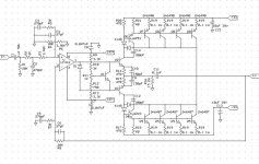
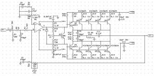
I don't know those power transistors, but that opamp (a dual) is not a very fast one. It will have phase shifts at higher audio freqs. That's also why you see those phase correction networks on the inputs and feedback leg. I think this amp is robust, rugged, almost undestructible, but may have more hf THD than necessary using modern components. And no, you CANNOT plug in another (fast) opamp and hope it will be OK. And yes, as said above, the C1 is too small for good lf response. C5? That's for phase correction, I asssume it is correct, but there's no quick and easy way to say it is or isn't.
Those 1N4148's are there to keep the output transistors from saturating when driven to max output voltage. Seeing that old technique used here, I get suspicious that they are quite slow (low Ft).
Jan Didden
Those 1N4148's are there to keep the output transistors from saturating when driven to max output voltage. Seeing that old technique used here, I get suspicious that they are quite slow (low Ft).
Jan Didden
Yep I Based this design on a circa '87 amp design. I have already gone through the design and replaced some obsolete components with ones that are still in production. What kind of output transistors would be a suitable, modern replacement?
I am still fairly new at amp design, and want to thank everyone on this board for being helpful.
I am still fairly new at amp design, and want to thank everyone on this board for being helpful.
Last time I saw this Baker Clamp technique in audio was on the old Apt 1 Power Amp with some old Motorola output devices - kind of slow but rugged (for their time). I'm thinking you may want to use some other diodes here; I'm remembering FDH400 or something like that maybe for capacitance and leakage reasons?
janneman said:....
Those 1N4148's are there to keep the output transistors from saturating when driven to max output voltage. Seeing that old technique used here, I get suspicious that they are quite slow (low Ft).
Jan Didden
If you delete the MJE driver transistors and the Baker clamp it looks just like a Rockford Fosgate Punch 150, it only had two pair of outputs per channel.
When you slammed that amp hard those 10µF power supply bypass caps would blow their cans clear off the board! I found some 63V stacked film types with the same footprint.
"Last time I saw this Baker Clamp technique in audio was on the old Apt 1 Power Amp with some old Motorola output devices - kind of slow but rugged (for their time). "
The APT 1 used two pair MJ15022/23 outputs. Later versions were rated at 250W/2R, that's 16A collector current, 8A per pair. The gain-bandwidth product of these was 2.5Mhz at 8A.
The ever popular 2SA1302 is about the same, and the 2SC3281 is well below 2Mhz at this kind of current.
Hmmmmm ....
As my wife will attest, I humbly apologize for my obviously faulty memory.
mlloyd1
As my wife will attest, I humbly apologize for my obviously faulty memory.
mlloyd1
djk said:"....old Motorola output devices - kind of slow but rugged (for their time). "
The APT 1 used two pair MJ15022/23 outputs. Later versions were rated at 250W/2R, that's 16A collector current, 8A per pair. The gain-bandwidth product of these was 2.5Mhz at 8A.
...
Hey~! You might want to look into this...
http://www.audio-circuit.dk/LYNX_main.html
Has an Opamp on the input as well...
http://www.audio-circuit.dk/LYNX_main.html
Has an Opamp on the input as well...
- Status
- This old topic is closed. If you want to reopen this topic, contact a moderator using the "Report Post" button.
- Home
- Amplifiers
- Solid State
- How does this bipolar look?