Which of the 10 collected possibilities by post #1 aboutthis is not "The Royal" way.
It is one of a few correct ways to wire up the DC blocker.
http://www.diyaudio.com/forums/soli...t-buzzing-toroid-transformers-what-right.html
is from your view to avoid and which topology is the royal way?
I found the post you were referring to. I do wish you had placed a link direct to it.
I do not like any of those 10 options. They all seem to incorporate the same error. The fused line is different from the switched line.
Did you draw these up from other sources?
Yes. The sources are mostly mentioned in the schematics. The fact, that fused line must be the switched line, is correct. This isn't respect in my own drawings - partly an error from me, and partly through overtaken of one of the schematics. This I haven't exact investigate at the individual sources. Cause the use of the copy function in the CAD program this fatal error in terms of safety requirements is unfortunately in all examples.
But I'm interested in the actual differences between the DC filter topologies itself.
I cannot placed a link direct to it without upload to my own website. But I post the same pdf file with DC blocker schematic collection here. Unfortunately the mentioned URLs by the schematics mostly death in the meantime.
Attachments
Last edited:
Thank you for posting this topology. Must actually be the royal way and I have never see before in commercial products. The schematic collection, that I know from commercial products, you will find by post #1 about
http://www.diyaudio.com/forums/soli...t-buzzing-toroid-transformers-what-right.html
What is the reason for the choiced polarity of the electrolytic caps (positive pole to anode and negative pole to cathode)? The voltage in the reverse mode is commonly 1V (independend of the voltage values in normal mode).
I like this schematic, but have a question. Does it go on the hot mains line, or on the neutral? If you put it on the neutral, wouldn't you also have to put it on the ground from the PT center tap? I'm kind of uncomfortable messing around with the ground.
Also, would a thermistor on the hot line in front of this be ok? Say 40ohms going to less than one?
Thanks,
Todd
Hi Andrew,
I read through the debate on live versus neutral, and l guess I'm still a little confused.
If the neutral line gets interupted inside the chassis because the DC blocker failed in the open position, couldn't the current simply flow through the ground line?
And even if the ground line wouldn't conduct enough current to keep the amp running, if you only blocked the neutral line, wouldn't the ground path at least be sufficient for the DC to trickle through the toroid and cause it to hum?
Thanks,
Todd
The Ground line you are referring to is the Safety Earth.
It is connected to Protective Earth (PE) all the way back to the distribution board.
This is there for Safety only.
In normal non fault use the ground line does not carry current.
There are exceptions:
earth leakage.
capacitive grounding of HF interference.
It is connected to Protective Earth (PE) all the way back to the distribution board.
This is there for Safety only.
In normal non fault use the ground line does not carry current.
There are exceptions:
earth leakage.
capacitive grounding of HF interference.
The Safety Ground wire is connected to Mother Earth and one end and to your chassis at the other. No significant current should flow through this wire. (see Andrew's post above)
The Neutral wire is connected to Mother Earth and one end and to your power transformer at the other end. The Neutral wire must NOT be connected to your chassis.
Your Power Supply does not use the Safety Ground as a current path.
The Neutral wire is connected to Mother Earth and one end and to your power transformer at the other end. The Neutral wire must NOT be connected to your chassis.
Your Power Supply does not use the Safety Ground as a current path.

NP post #26:They had better be some pretty big Zeners
I use Thermistors in series with my AC line, and I find
that they are fairly good at suppressing the DC hum
problem by limiting the current through the primary,
which is usually 1/2 ohm or less. The Thermistor settles
into a value of an ohm or two, and the saturation current
goes way down. If you don't like the resistance of the Thermistor, then
you can bypass it with electrolytics, but for Class A amps
you simply figure the Thermistor drop into the equations,
as the draw is pretty constant.
Reply mlloyd1 - re: Nelson's last post # 26: Hmmm.... I use a high power, low value resistor (shorted by a relay after 7 seconds) as my soft-start circuit. I've noticed that when the powerline conditions are such that my transformer (big avel linberg 1200VA) buzzes, it doesn't buzz until the soft-start resistor is shorted.
I may play with Nelson's thermistor idea to see what happens.
Stay tuned .... Michael
Reply CBS240: Yes, that is what I observe too. In my case, I use an isolated control circuit that places the resistor in series via a photo-triac, which is then shorted by a relay. The 1400VA toroid only buzzes when the relay is activated and it is on the line. The series resistor near completely eliminates the triac switch noise, however using a triac switch in place of the relay causes the toroid to buzz with the switching action. I had to modify my control circuit for toroids. Incidentally due to higher flux leakage and core size an EI transformer does not react so harshly to the triac switch and is quiet. As for the 1400VA toroid it goes into spells. Most of the time it is quiet but when other appliances turn on it tends to buzz a bit. I wonder if one were to add primary turns to lower flux density (and rating) would it be less prone to "walk" into saturation by low frequency harmonic noise on the mains?
Interesting observations. Which Triac type is the best choice for soft switching on very large transformers?
Maybe an SGS Thomson alternistor like
http://www.datasheetcatalog.org/datasheet/stmicroelectronics/3205.pdf
is the best choice - but I am not sure
Last edited:
The advantages and disadvantages of locating the DC blocker in either the Live Line or the Neutral Line have been discussed at length. I will not try to repeat here.
DO NOT interfere with the PE to Chassis Safety connection.
This is a long thread to wade through! I don't think there was any concensus at the time as to whether it mattered if extra filter circuitry was in the active or neutral line - and I didn't read much discussion on the topic at all in this thread (maybe it was elsewhere).
In general, I think it is better to educate people to place additional circuit parts in the active, than the neutral, based on the generic safety standards that a fuse and a switch must be in the active, and a switch can only be in the neutral if it is ganged with an active switch. The aim being (if adding parts) to maintain as much circuitry as possible at a neutral level should any part fail.
The counter argument may be that if the added parts were bulky and/or susceptible to touch then it would be better if they were closer to neutral level during normal operation.
If the added parts were insulated from contact, even with the covers off, then I would probably prefer them in the active, as then the transformer primary is at neutral (ie. probing its terrminals).
Tim
I am of the opposite view, but I did not want to push my opinion on anyone. Let them read the discussion.
The mains fuse is always in the Live Line.
The switch (in the UK) is a two pole that simultaneously cuts both Lines.
The transformer Primary has two Line connections. One must be at Live voltage. Anyone probing or measuring, will know that and they will carefully bypass the insulation during the measurement.
The DC blocker on the other hand is bulky, has many connections, wires and terminals. It looks very similar to other low voltage parts inside the amplifier.
I consider it safer from accidental or ill-informed touching that it be in the Neutral Line. That is just my opinion.
If your house/country has non polar mains plug tops, then it does not matter.
In that case, everything can be at Live voltage !!!!
Look for the discussion and decide for your self.
Thanks for response Andrew, but I admit I can only identify posts 106-108 on this topic (two are by you, and one just agrees with you).
My enquiry was not per se to concrete in a view, but rather to tease out the issues that people perceive. The topic is about doing primary side wiring and safety (so it gets a big tick), and probably presents a big question mark or confuses many (eg. posts 165,167,169). I tried to search for the thread you refer to in post 106 but didn't get very far.
The topic is somewhat more generic, as it goes to applications like inserting in-rush limiters such as NTC thermistors and resistor bypassed relay contacts.
And as you say, the use of parts that are typically just found on the secondary side is a big cause for concern, and maybe that in itself needs to be more strongly heralded than it has to date (ie. no significant flag waving till your post).
Maybe the best outcome is that such a mod gets visually identified within the amp as hazardous primary circuit parts, and suitably documented for the next service person who opens up the chassis to faultfind a problem.
Ciao, Tim
Hi,
Attached a very simple circuit that is working since 29 years with a 1k5 Watt transformer.....(NOT a toroid BTW!) Of course this is a AC relay.
I have been using a circuit similar that from Elso for more than 12 years on my Futterman otl3e clones. Powering a 1000VA Toriod transformer up. I never had a blown fuse.
Simplicity at its best.
Claus
In post #82 of this thread, Elso Kwak, and then Claus reported excellent results with a soft-start, AC current in-rush reduction circuit comprising an in-line series resistor, bypassed by a relay contact, with the relay coil connected across the transformer primary. Depending on relay characteristic and resistance value, the resistor is in circuit for a soft-start time of nominally 0.5 second.
The circuit provided by Elso Kwak shows a 0.1uF across the resistor/relay contact. Now to my mind, I can't fathom why the capacitor is used in that position. Typically a cap (or RC) is placed across a contact to alleviate the impact of step current change to zero. But in this position, the relay contact would only open after the main AC switch has turned off the amp.
Am I missing something?
I'm just wiring in this resistor/relay configuration on a big amp at the moment, and was more inclined to put in an RC or MOV across the transformer primary (ie. relay coil).
Ciao, Tim
You are not missing anything.Now to my mind, I can't fathom why the capacitor is used in that position. Typically a cap (or RC) is placed across a contact to alleviate the impact of step current change to zero. But in this position, the relay contact would only open after the main AC switch has turned off the amp.
Am I missing something?m
The sequence of contacts opening determines which ones need spark erosion suppression.
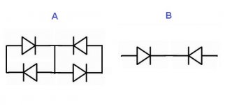
Questions.
What the forward voltage will be in each configuration (0.7 standard)?
What are the benefits of A over B and vice versa?
If the Caps are in series & back to back (+ to +) what would the combined Ripple Current will be?
Will it be safe to run all my equipment through a DC filter from one outlet & a power strip,
if the capacitors ripple current and capacitance will suffice?
Is a fuse is mandatory in the DC Filter box?
If yes what will the value would be?
(larger then the total consumption in amps and lower then the ripple current?).
The hum is from my Studio Monitors toroidal transformer that rated 110W (0.5A) 220V each.
I've read that in a small transformers all of this is insignificant.
So, am I doing it for nothing or will it help the small ones to?
P.S.
What I will use:
230v 50hz.
10A10 diodes (10A 1000V 1.0 Vf).
47000uF 16v 6.93A ripple.
Thanks.
Attachments
Andrew:
In other threads you talk about reverse voltage (forward Voltage?) of the capacitor itself;
thats why we want to put the caps back to back in series not in parallel like Bryston.
So putting the caps in series bypasses this danger of having max of about 1-1.5 Vf of the cap?
I chose high power diodes that combined will form about 2.2 Vf (~1.1 each); is it too high for the caps (same question)?.
- Home
- Amplifiers
- Solid State
- DC filter