I've just read some more into the circuit that I found and posted up a few threads back. The breakdown voltage of DIACs is anywhere between 28 and 36 volts, so this circuit will only work for amps with a supply voltage of -36 and +36 volts.
Because I'm only using + and - 25 volts, is there a simple dc protection circuit similar to this that I can use. I have searched everywhere.
Because I'm only using + and - 25 volts, is there a simple dc protection circuit similar to this that I can use. I have searched everywhere.
Has anyone used this method?
Also, TRIACS have a gate pin, would this be shorted to ground?
The circuit protection with a triac you've mentioned is already widely used in professional units and it's called a 'crowbar'. Here is a sample of QSC RMX4050 schematic, the part with DC protection.
An externally hosted image should be here but it was not working when we last tested it.
Thanks for the schematic. I have a couple of questions...
Can this circuit be fed from the output of the amp (the red speaker terminal)?
P1 is connected to power ground?
Will this work on a +25 and -25 volt amplifier?
Will it trigger with negative dc on the output? as I don't understand how the thyristor will fire with -ve dc.
How sensitive is this circuit, how many volts are actually needed to trigger the TRIAC and how long does it take to trigger? I suppose this depends on the value to the capacitor??
Can a larger amperage TRIAC be used in the circuit, maybe a 40A version?
Thanks in advance
Last edited:
Now I find the right title of this paper: "Ulti Amp" in Elektor German issue 5+6/94. Schematics also by post #3 and #4 aboutThe German magazine Elektor have release many amplifier diy projects in the last 30 years. between 1985 and 1998 I recall, that such TRIAC DC protector was realized by one of the projects. I have all magazines from this aera, but I don't know, how I find the right article
Here is an online register for German's elektor
Elektor Artikelsuche
but what is the right keyword/title for the appropriate amplifier project?
http://www.diyaudio.com/forums/elektor/11523-elektors-ulti-amp.html
A second amp with such DC protect there is - also from elektor. Title "The Current Amp" Nov/Dec 1992. Load impedance: 400 mΩ load and 35A peak output current. Also available in french:
http://209.85.129.132/search?q=cach...current+Amp"+elektor&cd=5&hl=de&ct=clnk&gl=de
(scoll down)
Great similarity to that one from QSC RMX4050 (post #22). But the fuses in the voltage rails for the output power buffer and not in series to the speaker signal.
Last edited:
Hi portreathbeach,
I'm afraid this circuit isn't suitable in your case since this circuit with two 2N5064, which acts like a DIAC, has a breakdown voltage over 30 Volts. Yes, P1 is power ground. Protection can be triggered with positive a negative voltage. C158 with R255 is placed to filter the AC, audio signal, otherwise the protection would be triggered in normal operating conditions. Any triac can be used. Of course, it must withstand the current drawn from the power supply.
Well, I would recommend using TA7317P mentioned before since it has a DC protection and 'anti-thump' feature which can be nicely adjusted. The circuit doesn't require many components. It is obsolete but you can still find it in stores. Or you can use the Elektor's circuit above, with triacs, tnx to tiefbassuebertr.")
I'm afraid this circuit isn't suitable in your case since this circuit with two 2N5064, which acts like a DIAC, has a breakdown voltage over 30 Volts. Yes, P1 is power ground. Protection can be triggered with positive a negative voltage. C158 with R255 is placed to filter the AC, audio signal, otherwise the protection would be triggered in normal operating conditions. Any triac can be used. Of course, it must withstand the current drawn from the power supply.
Well, I would recommend using TA7317P mentioned before since it has a DC protection and 'anti-thump' feature which can be nicely adjusted. The circuit doesn't require many components. It is obsolete but you can still find it in stores. Or you can use the Elektor's circuit above, with triacs, tnx to tiefbassuebertr.
Last edited:
Thanks HighTec.
Now, instead of a Crowbar circuit, I am now thinking of using a PIC microprocessor and output relay arrangement. The problem is, I want to be able to detect +ve and -ve DC on the output of the amp and then this will give me an input of either +5v or 0v to an input on my PIC which I can then use to control the output relay. I have tried several circuits with NPN and PNP transistors, but none seem to work together. They seem to work separately, detecting +ve or -ve, but when the circuits are put together, they don't work. Is there a simple circuit I can use?
Now, instead of a Crowbar circuit, I am now thinking of using a PIC microprocessor and output relay arrangement. The problem is, I want to be able to detect +ve and -ve DC on the output of the amp and then this will give me an input of either +5v or 0v to an input on my PIC which I can then use to control the output relay. I have tried several circuits with NPN and PNP transistors, but none seem to work together. They seem to work separately, detecting +ve or -ve, but when the circuits are put together, they don't work. Is there a simple circuit I can use?
Is there a simple circuit I can use?
Hm, depends what you mean by simple. Here is a sample of a protection circuit with a PIC microcontroller used in Crown's Pulse amplifiers. Unfortunately, microcontrollers are beyond my knowledge since they require programming.
http://img242.imageshack.us/img242/5924/pulse.jpg
Direct link for the Pulse 1100 schematic:
http://www.crownaudio.com/pdf/legacy/s-c1100as-03.pdf
Last edited:
rational discussion
Finally, after 8 weeks on this board, a rational discussion about speaker protection.The previous 555 timer thread was silly. Relays are too slow for lightning. I have been lurking on this thread for a week, but couldn't figure out how to see the original circuit without the previous post. My speaker cost 10x what the amp did; I'm still using a tube amp because of the transformer protection - good against lightning, too. I respect the capacitor comments, and the triac with trigger circuit comments. Don't forget to put a UL rated (or your local safety agency) MOS snubber up on input power transformer for lightning, if you are working on an old line frequency transformer transistor unit. Reduces power turn off snap, too, a tweeter tester transient.
Finally, after 8 weeks on this board, a rational discussion about speaker protection.The previous 555 timer thread was silly. Relays are too slow for lightning. I have been lurking on this thread for a week, but couldn't figure out how to see the original circuit without the previous post. My speaker cost 10x what the amp did; I'm still using a tube amp because of the transformer protection - good against lightning, too. I respect the capacitor comments, and the triac with trigger circuit comments. Don't forget to put a UL rated (or your local safety agency) MOS snubber up on input power transformer for lightning, if you are working on an old line frequency transformer transistor unit. Reduces power turn off snap, too, a tweeter tester transient.
The ultimate DC protection from Germany
the simplest DC protector ever made - manufactured by
News - GLOCKENKLANG
available by
GLOCKENKLANG OUTPUT TRANSFORMER 600 W.COVER - U.K. International Cyberstore
the same kind of DC protection is in use by some solid state amplifier models from McIntosh, e. g.
http://www.diyaudio.com/forums/soli...osh-ma-6800-ma6800-power-stage-schematic.html
and
http://www.zenn.com.sg/Marketplace images/Speakers/McIntosh_MC2300.JPG
http://mcintoshlaboratory.tripod.com/aa/mc2300.htm
http://www.mikesmanuals.com/Upload/McIntosh_MC2300_Service_Manual.jpg
http://www.mikesmanuals.com/Mikes_Manuals_MCINTOSH.htm
http://mcintoshcabinets.com/pages/mcintosh.htm
Attachments
Last edited:
So here is my DC speaker protection:
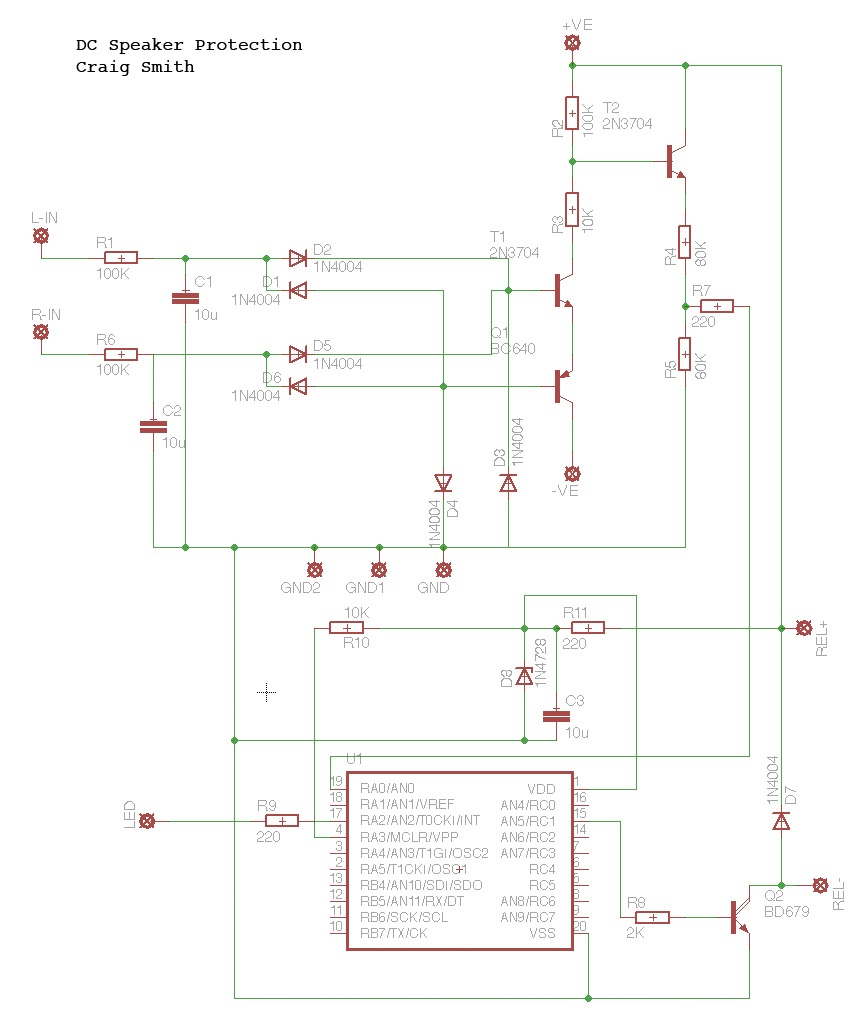
I used some schematics from Elliot sound products to help with this circuit.
L-In and R-In come straight from the speaker terminals, +ve and -ve are +25 and -25 volts from the power supply. When the circuit detects DC, transistor 2 is turned on and the 25 volts is dropped across R4 and R5 to give 5 volts. This can then be used by the PIC multiprocessor.
There will be 2 x 12 volt relays with there coils in series fed from Rel+ and Rel-. These will be used to break the speaker output. Obviously, because a PIC is used here, any delay can be programmed into it and it can also flash the LED when the detection is sensed.
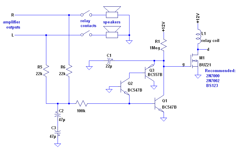
This is a classic dc protection
loudspeakar protection from DC w/ softstart - Page 2 - All About Circuits Forum
loudspeakar protection from DC w/ softstart - Page 2 - All About Circuits Forum
I need user name and password to download this PNG fileThis is a classic dc protection
loudspeakar protection from DC w/ softstart - Page 2 - All About Circuits Forum
That's a very similar circuit. Please can you explain the 2 x 47u caps?
Also, there are no diodes in this circuit, why does the design I based my schematic on use so many diodes?
Could the circuit be fed with +25v instead of +12v, so no other power supply would be needed in the amp?
Also, there are no diodes in this circuit, why does the design I based my schematic on use so many diodes?
Could the circuit be fed with +25v instead of +12v, so no other power supply would be needed in the amp?
Last edited:
why does the design I based my schematic on use so many diodes?
In case of an output device failure, diodes are necessary to block the negative or positive DC to flow from one channel to the other channel, which could certainly make a huge damage.
Last edited:
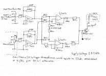
All these circuits so far rely on a time constant (to filter the audio) and although we all hope we never need the protection in practice, if we do... is it quick enough to prevent damage ?
Although I never developed this idea further (there should be a thread somewhere, although I can't find it), this working prototype aims to eliminate that delay by comparing input and output of amp. If there is a difference... the relay trips. The delay is now just that of the mechanical properties of the relay and the way the coil is driven.
Although I never developed this idea further (there should be a thread somewhere, although I can't find it), this working prototype aims to eliminate that delay by comparing input and output of amp. If there is a difference... the relay trips. The delay is now just that of the mechanical properties of the relay and the way the coil is driven.
Attachments
- Status
- This old topic is closed. If you want to reopen this topic, contact a moderator using the "Report Post" button.
- Home
- Amplifiers
- Solid State
- Another simple DC protection