Both NAP-140 and JLH1969 are classic power amp. I have built both a JLH1969 and the NAP-140 clone. I like both of these two amps, they sound much better than any of the commercial amp available to me. However, by comparing the two amps, I find the NAP-140 is kind of lacking bass, and also might be having higher THD. A respected professional has ever pointed out there are flaws in the NAP-140 clone schematic(see fig.1), and he also provided a "corrected" and "improved" design(see fig.3). Now I have given away my 1969 to my best friend. I want to modify the NAP-140 to have better sound than the 1969, in terms of THD at high output power, and bass performance. I have some specific questions on the schematic. Can any body help to answer?
Fig1. NAP-140 Clone Schematic
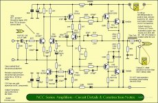
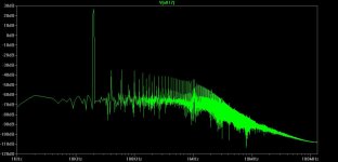
Fig2. NAP-140 Clone Simulation(occilating at high freq. around 100kHz)
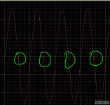
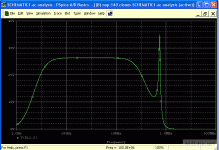
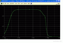
Fig3. Improved Schematic
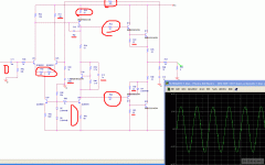
Fig4. Simulation for the Improved Design
My questions are
1) Is there any logic and theoritical explaination for the simulation result? Why the amp occilates at around 500k-800kHz?
2) What is the 68uF capacitor across TR5 for? What happen if I increase or reduce the capacitance?
3) I suspected the 68uF(actually 22uF in the Clone kit) capacitor along the negative feedback line to the tround would affect the base. I replaced Nichcon Muse 22uF with a 220uF electrolyte. Now I have deeper and lower base, but it still not tight and clean. Is there a way to improve?
4) Both channel DC offset at output is less than 5mV at quencent. However, when the amp is approaching to the full output power, the DC offset at the output is some times over a few hundreds mV(I know these because my speaker protection circuit come into play, which usually requires over 800mV DC). What is most likely the cause of this DC offset? How to improve it?
The PSU is a 200W 34v+34v transformer with single bridge(10A) and two 14000uF reservoir for both channel.
Fig1. NAP-140 Clone Schematic

Fig2. NAP-140 Clone Simulation(occilating at high freq. around 100kHz)


Fig3. Improved Schematic

Fig4. Simulation for the Improved Design

My questions are
1) Is there any logic and theoritical explaination for the simulation result? Why the amp occilates at around 500k-800kHz?
2) What is the 68uF capacitor across TR5 for? What happen if I increase or reduce the capacitance?
3) I suspected the 68uF(actually 22uF in the Clone kit) capacitor along the negative feedback line to the tround would affect the base. I replaced Nichcon Muse 22uF with a 220uF electrolyte. Now I have deeper and lower base, but it still not tight and clean. Is there a way to improve?
4) Both channel DC offset at output is less than 5mV at quencent. However, when the amp is approaching to the full output power, the DC offset at the output is some times over a few hundreds mV(I know these because my speaker protection circuit come into play, which usually requires over 800mV DC). What is most likely the cause of this DC offset? How to improve it?
The PSU is a 200W 34v+34v transformer with single bridge(10A) and two 14000uF reservoir for both channel.
Last edited:
---simulation cannot tell you much about the sonic signature of one amplifier
---highly experienced users with very powered software tools might be able to convert the info to a usable product regarding the sound
---The schematic of figure 3 will not operate properly its way too simplified and there is obviously beyond other mistakes very wrong choice of parts
---finally since you are constructing the amp from scratch why not convert it to a full complementary which now days will be better, more stable, faster and more tollerant than a quasi
Hi,
In my opinion, you'd better use the original version, not the NCC-200 and for sure not the improved circuit 3.
I think that unmodified NAP-140 clone has better sound than the 1969 JLH, in terms of power and bass.
I wouldn't believe 100% simulated results, but in general, this amp oscillates when the used transistors are not suitable (not fast enough) and when the circuit is not properly compensated with the correct Miller capacitor around TR4.
It forces transistor TR5 in controlling only the DC component (in this case creating some constant voltage between collector-emitter), because the AC audio signal is bypassed through the capacitor. By the way, in your modified version this capacitor is 0.1uF and must be around 100uF.
There is not 22uF in the NAP-140 clone. For the feedback 220uF is fine, most of us use about 100uF. Bass is not clean because there is distortion due to imbalance in the input differential transistor pair. Also, use the input resistor combination as in the original schematic. 2.7k/24k is OK, 4.7k/22k is OK, 1k/22k is not. This will affect the DC at the output
The reason may also be an oscillation.
In addition, it may be the imbalance in the differential pair currents. How did you come with 1.4kohms value? This is not a good value with the given current source current. I'd suggest to stick to the 1k/22k combination and only change the 620 ohms resistor to 560 ohms for better matching with the transistors that are used nowadays in the current source circuit (TR3). I wouldn't recommend any degeneration resistors bigger than 22 ohms for this circuit, or you'll need to sink more current in the current source.
Good enough for the NAP-140
In my opinion, you'd better use the original version, not the NCC-200 and for sure not the improved circuit 3.
I want to modify the NAP-140 to have better sound than the 1969, in terms of THD at high output power, and bass performance.
I think that unmodified NAP-140 clone has better sound than the 1969 JLH, in terms of power and bass.
1) Is there any logic and theoritical explaination for the simulation result? Why the amp occilates at around 500k-800kHz?
I wouldn't believe 100% simulated results, but in general, this amp oscillates when the used transistors are not suitable (not fast enough) and when the circuit is not properly compensated with the correct Miller capacitor around TR4.
2) What is the 68uF capacitor across TR5 for? What happen if I increase or reduce the capacitance?
It forces transistor TR5 in controlling only the DC component (in this case creating some constant voltage between collector-emitter), because the AC audio signal is bypassed through the capacitor. By the way, in your modified version this capacitor is 0.1uF and must be around 100uF.
3) I suspected the 68uF(actually 22uF in the Clone kit) capacitor along the negative feedback line to the tround would affect the base. I replaced Nichcon Muse 22uF with a 220uF electrolyte. Now I have deeper and lower base, but it still not tight and clean. Is there a way to improve?
There is not 22uF in the NAP-140 clone. For the feedback 220uF is fine, most of us use about 100uF. Bass is not clean because there is distortion due to imbalance in the input differential transistor pair. Also, use the input resistor combination as in the original schematic. 2.7k/24k is OK, 4.7k/22k is OK, 1k/22k is not. This will affect the DC at the output
4) Both channel DC offset at output is less than 5mV at quencent. However, when the amp is approaching to the full output power, the DC offset at the output is some times over a few hundreds mV(I know these because my speaker protection circuit come into play, which usually requires over 800mV DC). What is most likely the cause of this DC offset? How to improve it?
The reason may also be an oscillation.
In addition, it may be the imbalance in the differential pair currents. How did you come with 1.4kohms value? This is not a good value with the given current source current. I'd suggest to stick to the 1k/22k combination and only change the 620 ohms resistor to 560 ohms for better matching with the transistors that are used nowadays in the current source circuit (TR3). I wouldn't recommend any degeneration resistors bigger than 22 ohms for this circuit, or you'll need to sink more current in the current source.
The PSU is a 200W 34v+34v transformer with single bridge(10A) and two 14000uF reservoir for both channel.
Good enough for the NAP-140
Last edited:
hi Sakis,
For diyers, quasi-complementary pair is an easy choice that simply easier to construct due to parts availability. Diyers, such as me, normally do not have instruments to match power transistors. Why you think "full complementary which now days will be better, more stable, faster and more tollerant". I would like to see some theoritical ground. Could please provide some reference? Thank you.
For diyers, quasi-complementary pair is an easy choice that simply easier to construct due to parts availability. Diyers, such as me, normally do not have instruments to match power transistors. Why you think "full complementary which now days will be better, more stable, faster and more tollerant". I would like to see some theoritical ground. Could please provide some reference? Thank you.
Last edited:
Ruwe,
Thank you very much for your answers.
Many the parts are not available, which prevent me to construct a unmodified NAP-140. Also, by using modern transistors, can we reproduce the sound of an original NAP-140? Or can we even get a better sound by using modern parts with the same schematic?
With regard to the cap around TR4, mine is a 56p. I see most of the design using 39p-68p. By the way, in my construction, I use Hitachi 2SB649 for the TR4. Could there be a better choice? My measurement show that the static current through TR4 is 7-8mA, which produces 300-400mW. Normal To-92 transistors could not sustain and work stably under that condition. So did my first and second construction, both a 2SA1145 and a BC556C with heat sink have been used for TR4, both blowned away.
Here are some datasheet for those interested.
The schematic for my first and second construction.
View attachment h140.pdf
2SB649 datasheet
View attachment 2sb649.pdf
2SA1145 & 2SC2705 datasheet
View attachment 2sa1145.pdf
View attachment 2sb649.pdf
BC546 & 556 datasheet
View attachment BC556.zip
View attachment BC546_7_8.pdf
IRF540N
View attachment IRF540N.pdf
The "Improved" NAP-140 Schematic
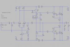
LTspice Simulation - AC sweep for the "Improved" NAP-140

From LTspice simulation result, that modified circuit does have very attractive performance
Thank you very much for your answers.
Many the parts are not available, which prevent me to construct a unmodified NAP-140. Also, by using modern transistors, can we reproduce the sound of an original NAP-140? Or can we even get a better sound by using modern parts with the same schematic?
With regard to the cap around TR4, mine is a 56p. I see most of the design using 39p-68p. By the way, in my construction, I use Hitachi 2SB649 for the TR4. Could there be a better choice? My measurement show that the static current through TR4 is 7-8mA, which produces 300-400mW. Normal To-92 transistors could not sustain and work stably under that condition. So did my first and second construction, both a 2SA1145 and a BC556C with heat sink have been used for TR4, both blowned away.
Here are some datasheet for those interested.
The schematic for my first and second construction.
View attachment h140.pdf
2SB649 datasheet
View attachment 2sb649.pdf
2SA1145 & 2SC2705 datasheet
View attachment 2sa1145.pdf
View attachment 2sb649.pdf
BC546 & 556 datasheet
View attachment BC556.zip
View attachment BC546_7_8.pdf
IRF540N
View attachment IRF540N.pdf
The "Improved" NAP-140 Schematic

LTspice Simulation - AC sweep for the "Improved" NAP-140

From LTspice simulation result, that modified circuit does have very attractive performance
Attachments
With regard to the cap around TR4, mine is a 56p. I see most of the design using 39p-68p. By the way, in my construction, I use Hitachi 2SB649 for the TR4. Could there be a better choice? My measurement show that the static current through TR4 is 7-8mA, which produces 300-400mW. Normal To-92 transistors could not sustain and work stably under that condition. So did my first and second construction, both a 2SA1145 and a BC556C with heat sink have been used for TR4, both blowned away.
The cap value is arbitrary and is selected by estimating the stability of the circuit. Smaller is better, because it will give you more open loop gain at high frequencies, hence less high freq. distortion. However, too small will cause oscillation. The cap value is very dependent on the current in the differential pair. If you set it for more current, you can increase the cap, and vice versa, without affecting the end result. See D. Self book for details. If you use degeneration resistors, you'll have to increase the current or reduce the capacitor to keep the same open loop gain and stability margins.
IMO, the original circuit without the degeneration resistors is correctly designed in this regard. And the current is just enough to drive Tr4, which is enough driven itself to drive the drivers at their specified currents.
It's deceptively simple schematic, but anything has a meaning, it's not over-engineered, but the designer definitely knew its craft. I think it was additionally fine tuned during lab tests (for example the R/C groups in the driver bases). Of course all that with their choice of transistors.
Tr4 is a critical one. I don't know which one is the best choice. I use ZTX792A. Generally, the right choice is highest possible bandwidth with the highest possible gain, plus enough current/power capability, which is usually self excluding. The role of the drivers is also very important, considering the fact that Tr4 drives them and is loaded by them. Same considerations are valid for them as well. My choice is MJE243/253.
Regards
Last edited:
Some more modification & simulation
Prior to my third time to take the amp apart, I have done some simulation work. As Ruwe pointed out that there might be some occilation due to inappropriate cap/TR4. So I tried to build a Spice model with solely bjt.
The revised schematic
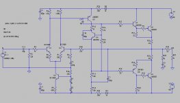
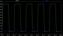
Simulation 50K Square Wave
Simulation 20K Sine Ware & FFT
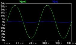
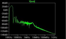
I have tried different combination of Q5 and C5. The result show that different Q5 does not make much difference as long as it is a high Ft small signal device. Meanwhile, the C5 introduce distortion at high freq. The higher the capacitance, the bigger the distortion. From the above simulation graph, we see that C5 is best as removed, given the output pair is low Ft transistor such as 2N3055.
By the way, I have very limited bjt/mosfet models in my LTspice library. Does anybody know where to get more models? Thanks a lot.
Prior to my third time to take the amp apart, I have done some simulation work. As Ruwe pointed out that there might be some occilation due to inappropriate cap/TR4. So I tried to build a Spice model with solely bjt.
The revised schematic

Simulation 50K Square Wave

Simulation 20K Sine Ware & FFT


I have tried different combination of Q5 and C5. The result show that different Q5 does not make much difference as long as it is a high Ft small signal device. Meanwhile, the C5 introduce distortion at high freq. The higher the capacitance, the bigger the distortion. From the above simulation graph, we see that C5 is best as removed, given the output pair is low Ft transistor such as 2N3055.
By the way, I have very limited bjt/mosfet models in my LTspice library. Does anybody know where to get more models? Thanks a lot.
Last edited:
removed C5 from on channel (refer to the above schematic). The sound becomes cristally clear. I can hear much more fine tunes of very high notes. Sadly, later, I found that the head sink becomes very hot. Cannot touch it with bear hand. Power off, Cool down, and power on again, the quiscent current seems not stable. It could jump from a few mA to hendreds of mA in few second, which seemed to be triggered by the input signal.
your are on a very wrong road my friend ....
miller caps provide stability and determine the usable frequency expand for a transistor...removing the capacitor will let free the circuit to oscillate....ideally you could locate the source of oscillation and eliminate it ... but this will only happen in a an ideal world with ideal transistors ,loads and so on
this can also be pcb related issue ...
then again removing it or lowering the value is a thing that can only be verified by instruments and someone that knows also how to use them
obviously simulators will also not tell you much about your pcb or load or cables and so on
I later on tried 4.7pF for C5, but that seemed worse than having C5 off circuit. It sometime gave audiable resonance noise from the speaker. According to the simulation, the C5 is a bottle neck that slow the amp down, ie. lead to low slew rate. Any idea how to modify the circuit and make it faster? The Naim design seems good for the turn table era, but not so good for the modern digital music sources. This is only my own opinion...
I think you could try the two-transistor correction Douglas Self applies to stages like that on the Naim.
Basically you would have to add a transistor and cut some pcb tracks, but it shouldn't be too hard.
Be noted that this doesn't eliminate the Cdom capacitor, which as Sakis said provide stability.
Perhaps you could try this mod on the simulation first and see what you get.
Basically you would have to add a transistor and cut some pcb tracks, but it shouldn't be too hard.
Be noted that this doesn't eliminate the Cdom capacitor, which as Sakis said provide stability.
Perhaps you could try this mod on the simulation first and see what you get.
Hi
Hi everybody
This is my first post in such a great place . The reason that i am posting here is that i just received two NAP-140 clones that i bought .And i am thinking to connect them to a switching power supply +-36V . adjustable to 40V like the one here:SMPS300RE 36V Dual Voltage 300W 230V Power Supply Connexelectronic | eBay
Has anybody used similar PS in AB class Audio amps?
the 140 is an honest amplifier without any ideas for wanting to excel between the audio amplifiers.
But it lends itself to several rather simple interventions.
I was thinking of modifying the input stage using a dual j fet cascode-loaded
a trimmer on the junction of the input torque emitters to better control the offset
delete the cap IN
use two pairs of power final transistors per channel
feed everything at 50 volts
change drivers with MJE 15000 series
if you want you could also use power transistors P and N instead of only N
Last edited:
- Status
- This old topic is closed. If you want to reopen this topic, contact a moderator using the "Report Post" button.
- Home
- Amplifiers
- Solid State
- Modified Naim NAP140 Schematic

