I am to publish the documentation when ready.
This is a simple, standard electronic circuitry, off the shelf part, inexpensive and may be found useful universal audio amplifier which allows for most any configuration of the 4 channels. All can be made mono and displayed on one of the stereo outputs only, or on the two stereo outputs. Any can be combined with any and displayed on any of the two outputs. Thus, a possible application is to play music from, say the "Immigrant Song" on the two channels in stereo fashion while playing the solo and displaying this on one of the outputs and singing and displaying the voice on the other. Or the music can play on one of the channels in mono fashion while the guitar and the voice are on the other thus allowing a direct competition to Robert Plant and Jimmie Page.
This is achieved very simply NOT by electronics but by simple configuration single pole double throw switches as well as a few on off switches.
THE CIRCUIT HAS NOT BEEN TESTED BECAUSE THE CIRCUIT HAS NOT BEEN BUILT. THE AVAILABILITY OF THE PARTS HAS BEEN CONFIRMED. THE CIRCUIT HAS BEEN DONE OVERNIGHT AND THERE MAY BE SOME MISTAKES ALTHOUGH SUCH ARE NOT EXPECTED BECAUSE OF THE SIMPLICITY AND THE STANDARD APPROACH. IMPROVEMENTS, CORRECTIONS, COMMENTS, SUGGESTIONS ARE POSSIBLE AND WELCOME.
Attachments
Last edited:
The universal audio amplifier uses standard electronics circuitry only and is built with components largely available in the local stores.
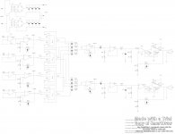
The goal has been to create an inexpensive “analogue studio”, i. e. a multi channel audio “system” which has an independent for each channel pre amplifier with separate adjustable “pre” gain, an adder (mixer) which allows for signal combination into two output channels to achieve stereo sound. The amplifier has been designed to be powerful enough to satisfy the general purpose home needs and may be found useful for rehearsals, garage bands, outdoor performance, parties, etcetera.
This is a simple, standard electronic circuitry, off the shelf part, inexpensive and may be found useful universal audio amplifier which allows for most any configuration of the 4 channels. All can be made mono and displayed on one of the stereo outputs only, or on the two stereo outputs. Any can be combined with any and displayed on any of the two outputs. Thus, a possible application is to play music from a released song on the two channels in stereo fashion while playing the solo and displaying this on one of the outputs and singing and displaying the voice on the other. Or the music can play on one of the channels in mono fashion while the guitar and the voice are on the other.
This is achieved very simply by simple configuration single pole double throw switches as well as a few on off switches.
Principle
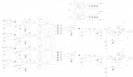
Power Supply:
Two standard off the shelf 110V AC to 18V AC, 1.85A transformers, T1 and T2, have been used to achieve a three point 36V DC, 1.85A (67W) power supply. These are not available in the general purpose stores, otherwise.
The inputs to the transformers (primary) have been paralleled with the outputs (secondary) put in series. Two standard 2A bridges, B1 and B2 rectify the two 18V voltages. In case of lack thereof, these can be made by 8 simple 2A diodes. The voltages at the output of the bridges are expected to be 18V – 2 * 0.7V = 16.6V. The voltages are averaged by the power supply filtering capacitors C01 and C05 and the RMS voltages are achieved. C02 through C04 and C06 through C08 are to filter spikes of switching noise, transients, etcetera and are chosen to be throughout the standard capacitive range without defined values. They can range 1µF, 1nF and 100pF, all >=18V, for example. A good idea is to keep: C02=C06; C03=C07; C04=C08.
C01=C05=220µF, >=18V or as big as possible electrolytic capacitors. The greater the value the better the filtering of the ripple effect.
The array of capacitors is something which I have made up and you are not expected to follow. Simply, do not install C02 through C04 and C06 through C08. To save more money and room, you may install only one capacitor between Vcc and Vee with as big as possible value and rated at >=36V. Huge 3.3mF (milifarads) capacitors are available at very inexpensive price these days at the local shops. Their diameter is like a coffee mug with 1” height.
The negative of one of T1 is connected to the positive of T2 to achieve the middle point (ground).
Buffers:
Four independent channels are buffered by OA1 through OA4. All operational amplifiers are TL084 or parts thereof.
Resistors R11 through R14 are for protection with a typical value of 10K and may be unequipped for noise reduction purposes thus exposing the JFET inputs of OA1 through OA4 to the environment.
Resistors of the same value may be put in the feedback (not logical feedback resistors) just to equalise the bias which is not necessary for sound because the bias is either DC or incredibly slowly changing and will be filtered thereafter. This is supposed to be incredibly small in mother operational amplifiers and, in not so high gain amplification, these are not supposed to bring the operational amplifiers to saturation.
TL084 is internally compensated for unity gain stability and may not be further compensated. Most modern operational amplifiers are although some manufacturers may still make uncompensated operational amplifiers because of the faster speed and stable operation at gains higher than one. A phase compensator (a resistor and capacitor) are needed to be installed at the provided pins of these. Most likely, none of you would use these operational amplifiers because TL084 as well as most modern operational amplifiers are fast enough, definitely more than enough for general purpose sound amplification. TL084 has a Unity Gain BandWith (UGBW), a. k. a. frequency of transmission ft, a. k. a. transmission frequency at 3MHz, which makes amplification with a gain of 150 possible with performance at the audio range 20Hz to 25KHz.
Pre Amplifier:
The signals enters the preamplifiers built around the operational amplifiers OA21 through OA24 (TL084). Pay attention on the design of the pre amplifiers by non inverting circuit decisions. This means there will always be a gain of at least 2 regardless of the value of the potentiometers P21 through P24 unless these are off to big potentiometers (not sure whether these are available), i. e. potentiometers which can be switched off (infinite resistance), and, when they are switched on, they would immediately go to their maximal resistance as opposed to 0, as most of them may be.
Please, pay attention on something more important: On one hand, the non inverting amplifier circuit is preferable because of the huge input impedance but, on the other hand, the previous stage (the buffers in this case) cannot get any current through which may lead to a non linearity distortion. Hence, most people prefer the inverting amplifier circuit. You are very welcome to switch to this. Also, the inverting amplifier schematics would go from 1 to the maximal gain which may be important for rare cases where the output voltage must not be high and the input voltage is unknown, hence the user is supposed to turn the gain down and gradually increase the gain (in case necessary) until the desired level for a specific application.
Something which I consider a great disadvantage of the inverting preamplifier circuit but all of the rest say there isn’t such, is the inability to ground the potentiometer of the non inverting preamplifier circuit. Again, I am probably one of a few who claims this and you are not expected to follow. I am afraid from these “antennas”, called potentiometers more than Jesus from the cops. Also, most would tell you say, a pot in the R1 circuit of the inverting amplifier circuit goes to low resistance of the previous stage and can’t pick too much noise. True, the noise would rather go to ground through the low output impedance of the previous stage but the other end of the resistor is in the feedback and any noise in the feedback would force the operational amplifier to adjusts its output accordingly to accommodate the noise just the same as the operational amplifier does to accommodate the feedback current (the current through R1 and R2 of the inverting amplifier circuit).
Anyways, I have decided to use the non inverting circuit and thus the buffers may be skipped because of the huge input impedance of the non inverting circuit, mainly in low gain application. The lower the gain, the more deep the feedback, the more like but not the same the amplifier performs like the buffer circuit. The less overall gain and the higher the open amplification (open gain, when the operational amplifier IC is not feedbacked), the higher the input impedance and the lower the output impedance.
I, however, prefer to keep the buffers because I am sick and tired of lousy sources of electrical signals. However, when known every operational amplifier used introduces non linearity distortions as well as noise, you may as well skip as much circuitry as you wish. For example the buffers.
Anyways, the pre amplifiers are built around the operational amplifiers OA21 through OA24 (TL084), resistors R211 through R241 (10K) and R212 through R242 (130K), capacitors C21 through C24 (47pF, >=18V) and potentiometers P21 through P24 (100K, >=1/4W (1/2W standard)).
Capacitors C21 through C24 are for pseudo filtering of frequencies higher than 25KHz. Real filtering is not possible because, at best, the high frequencies will be repeated at the output with a gain of 1 because of the gain function of the non inverting amplifier circuit:
G = 1 + R2x2 / R2x1
Even when R2x2 = 0, G is still equal to 1 and not to 0.
I’ve heard some people would even use a capacitor in series to the positive input of the non inverting amplifier circuit. This would stop the DC component with a cut off frequency of almost 0. Almost 0 because of the huge input resistance of the non inverting amplifier circuit:
fc = 1 / (2πRC)
fc ~ 0 when R -> ∞
However, this is NOT a good idea because the capacitor would stop the bias DC current on one of the pins (positive) only and there would not be compensation of the bias current on the other pin but most importantly because the capacitor would start charging by the DC component and this capacitor will become a source of input DC voltage to the non inverting amplifier and would saturate the operational amplifier’s output. However, some of the operational amplifiers have huge open gain input impedance and to charge a capacitor to this level may as well take several years or decades.
I do NOT recommend this, though.
The full gain formula of the pre amplifier is:
G = 1 + (R2x2 || Xc) / (R2x1+P2x), where:
Xc = 1 / (j ω C2x) = 1 / (2 π R2x2 C2x)
and
x replaces 1, 2, 3, 4.
When P2x = 0, then G = 1 + 130K / 10K = 14 (maximal gain of the preamplifier)
When P2x = 0, then G = 1 + 130K / 110K = 2.18 (minimal gain of the preamplifier)
Thus, each channel would have own amplification. At present, no provision has been made to allow for adjustment of bass and treble of each of the channel individually. This can be done easily by copying the stereo bass and treble adjustment circuit towards the output of the schematics for and pasting this to each channel after the pre amplifier, for example.
Provision for taking the signals after the pre amplifiers has been carried out via the outputs: OutP1 through OutP4 (OutPx).
Switches:
The switches are the most interesting part of the universal audio amplifier. Switches are not part of the electronics engineering but are rather a question of simple arrangement.
[ … more to follow … ]
Adder:
A simple inverting adder has been designed to play a mixer.
[ … more to follow … ]
Power Output Stage:
More amplification has been provided at the power output stage. The reason to have amplification close to the input, provided by the pre amplifier, is not only to equalize the signal levels but also to allow for amplification as close to the input as possible in order for the rest of the electronics to deal with large signals and not to be affected by a possible noise to be picked up on the signals’ path throughout the circuitry. HOWEVER, this has a drawback: the lower the signals the operational amplifiers deal with, the lower the nonlinearity. Because of this noise / nonlinearity controversy, a provision of two gain adjustments (close to the input, at the preamplifier and close to the output, at the power stage) to allow for the user to make the compromise accordingly.
Engineers don’t like noise, musicians: nonlinearity. Take ones, hit the others. Thus an engineer/musician will always be hit or will be hit double. Or never.
[ … more to follow … ]
Schematics
All resistors are 5%, 1/4W. All capacitors are >=18V.
ATTENTION: THERE IS A POSSIBILITY TO SHORT THE OUTPUTS OF THE PRE AMPLIFIER WITH THIS ARRANGEMENT OF THE SWITCHES. TL084 ALLOWS FOR THIS BUT THIS MUST NOT BE USED. 10K RESISTORS MAY BE CONNECTED TO THE OUTPUTS OF THE PREAMPLIFIERS AND THEN A BUFFER MUST BE PUT AT THE INPUT OF EACH OF THE ADDERS TO REMEDY THIS PROBLEM.
I would not use Spice even if they pay.
Spice is not a way to design circuits. The only way is full analisys of each chain and the connection of all chains. This schematic is very simple and built only by standard, simple and well known chains. However, even the complicated ones must be done the same way: full analysis and mathematical derivations from square1.
This is also very quick because electronics is simple and there is not much to analyse or think in 99% or even 100% of the cases.
Spice can be used ONLY to check your calculator, i. e. one can find a "typo" or a calculation mistake in some but not all cases.
The same applies for circuit evaluation after being built. However, while building the circuit one has the possibility to look and find some mistakes.
Simple logical thinking and basic mathematics are the only tools in electronics design. These can be helped tremendously by creating a cook list: list all things to check in all cases and go through each and every one of them. Some points may be glanced upon because of the relevance or importance for a given case. Others need more thorough look into.
So, I will never use Spice. If you have found any mistake, you are welcome to share your finding. If not, have a nice Spice evaluation.
I USUALLY MAKE A LOT OF MISTAKES, SO DO NOT TRUST WHAT YOU READ. YOU MUST CHECK ALL OUT.
Stanley, is it comedy circus going on?

Last edited:
An externally hosted image should be here but it was not working when we last tested it.
Spice can be used ONLY to check your calculator, i. e. one can find a "typo" or a calculation mistake in some but not all cases.
I USUALLY MAKE A LOT OF MISTAKES, SO DO NOT TRUST WHAT YOU READ. YOU MUST CHECK ALL OUT.
StanleyEngineers don’t like noise, musicians: nonlinearity. Take ones, hit the others. Thus an engineer/musician will always be hit or will be hit double. Or never.
Are you fan of Jon Lajoie ?
Last edited:
Another resistor is to be put to the input switches, so the inputs can be switched either to none (infinite input impedance (limited by the input impedance of the operational amplifier)) or to a higher value resistor (1M) or th a lower value resistor (10K) for a microphone. Capacitors may be introduced in parallel but the calculation is tricky because of a possible output capacitor of the previous stage. The resistors are connected to a low output impedance to a previous stage (in AC, at least) and to ground. Still, there will be noise mainly with the 1M resistor and without any.
Another output of the pre amplifier is to be put with as high as possible capacitive decoupling.
Capacitor before the speaker is OK in theory but, in order for the capacitor and a possible worst case scenario of 4 Ohm speaker not to filter higher than 20Hz, the value of the capacitor is 2mF non electrolitic which is not easy to achieve. Instead, balance resistors for the bias of the operational amplifiers (in the feedback of the buffers, for example or the positive pin of the non inverting amplifier) may be introduced to reduce the bias. However, tiny DC would remain and, hopefully, DC remains tiny after amplification because this would be put through 4 Ohm load in the worse case.
Instead of 2 18V AC power supplies (transformers), 3 PC supplies can be used, serialising their 12V outputs. Middle point can be provided in the fashion of the pre amplfier post which I have earlier made. The transistors of the middle point circuit will take double the current of the transistors of the two outputs.
I do NOT know who this person is but the quotes are true, though funny.
Thank you for laughing!
Thank you for laughing!
An externally hosted image should be here but it was not working when we last tested it.Stanley
Are you fan of Jon Lajoie ?
The whole electronics is a comedy circus, isn't it?
I meant, those who are interested and want to build similar circuitry, or those who want to make those who may be interested happy might as well wish to check all mistakes out.
Generally, this would be easy because everything is standard.
I meant to also say, I am one of these who make a lot of mistakes and I am not afraid to say this.
I am even proud! I think this shows I am normal!
Stanley, is it comedy circus going on?
Wonder what "class" your output stage operates in?
Regards,
_-_-bear
At first glance "no class" but for the 'nit picky' that amp is technically class C in that the devices conduct less than 180 degrees. Can you say cross-over distortion - and lots OF it? He'd be much better off with a chip-amp. That front end is a mess and will likely oscillate like mad. I take it this is not Steven's day job.
G²
I believe you refer to some comments I have made before but you do NOT want to say your oppinion directly. In case so, I am not unhappy because you have found mistakes but rather because you do not say this. However, I am used to these kind of people too. AGAIN: DO NOT BE FRUSTRATED, I HAVE CLEARLY SAID I DO NOT KNOW THE SITUATION.
The amplfier class, in the generally accepted terms is class AB or PUSH/PULL. The two of these TERMS, I consider to be useless and made by people who wanted to make science of 2 + 2 = 4.
The real "class" name, I would give is class "Amplifier with two half wave common collectors". This says everything: half wave: one conducts positive the other negative. Common collector: standard. The only things I would like to use as terminology are: common emitter, collector and base. The rest of the terminology is redundant. Can be said with explanatory words just as fast, unless you are a musician and care a lot to keep the tact when you talk.
Yes, I have been making calculations with each of them conducting fully. This is either because of safety or a mistake caused y the power calculation of the load.
For safety, I would like to calculate the very worst case. In this case is 18V. + or -. This is the power supply. Regardless of circuitry, where logically this may be impossible under normal opperation even when fried (operational amplifier saturated to -18 or +18 (+16.5, I take as 18) and a capacitor, I assume the capacitor may be fried and one of the transistors would be fully open and the capacitor will be welded. Thus full power supply will be going through the transistor (Vce assumed to be 0) and the load (worst case 4 Ohm, can be even 2 when paralleled). Thus 18/4=4.5A would be the worst case. THE BEST IS TO TAKE 36V, HENCE TO GET 9A TRANSISTORS EVEN WHEN THE MAXIMAL CURRENT UNDER NORMAL CIRCUMSTANCES IS 1.5A, although the parameters may deteriorate. In most posts I have chosen 6A with which I have broken the principles I have made.
I have been probably making the mistake to say the whole power gets into each transistor and this is half power. I explained the correct one when I explained the principle of work. In case I have to analyse the psychological origin of the mistake is because I have thought a lot of the power at the load. Or just didn't think this over at this period. And I usually do not check these circuits because I consider them very simple what they are but I MUST (BUT DO NOT) check even the simplest things. I di check these only in some circumstances as for example for work or when I build something (but depends on the purpose and what).
Instead of so much typing, you could have just said or commented or asked directly.
Wonder what "class" your output stage operates in?
Regards,
_-_-bear
Short answer: Class "Two Half Wave Common Collectors".
I believe you refer to some comments I have made before but you do NOT want to say your oppinion directly. In case so, I am not unhappy because you have found mistakes but rather because you do not say this. However, I am used to these kind of people too. AGAIN: DO NOT BE FRUSTRATED, I HAVE CLEARLY SAID I DO NOT KNOW THE SITUATION.
The amplfier class, in the generally accepted terms is class AB or PUSH/PULL. The two of these TERMS, I consider to be useless and made by people who wanted to make science of 2 + 2 = 4.
The real "class" name, I would give is class "Amplifier with two half wave common collectors". This says everything: half wave: one conducts positive the other negative. Common collector: standard. The only things I would like to use as terminology are: common emitter, collector and base. The rest of the terminology is redundant. Can be said with explanatory words just as fast, unless you are a musician and care a lot to keep the tact when you talk.
Yes, I have been making calculations with each of them conducting fully. This is either because of safety or a mistake caused y the power calculation of the load.
For safety, I would like to calculate the very worst case. In this case is 18V. + or -. This is the power supply. Regardless of circuitry, where logically this may be impossible under normal opperation even when fried (operational amplifier saturated to -18 or +18 (+16.5, I take as 18) and a capacitor, I assume the capacitor may be fried and one of the transistors would be fully open and the capacitor will be welded. Thus full power supply will be going through the transistor (Vce assumed to be 0) and the load (worst case 4 Ohm, can be even 2 when paralleled). Thus 18/4=4.5A would be the worst case. THE BEST IS TO TAKE 36V, HENCE TO GET 9A TRANSISTORS EVEN WHEN THE MAXIMAL CURRENT UNDER NORMAL CIRCUMSTANCES IS 1.5A, although the parameters may deteriorate. In most posts I have chosen 6A with which I have broken the principles I have made.
I have been probably making the mistake to say the whole power gets into each transistor and this is half power. I explained the correct one when I explained the principle of work. In case I have to analyse the psychological origin of the mistake is because I have thought a lot of the power at the load. Or just didn't think this over at this period. And I usually do not check these circuits because I consider them very simple what they are but I MUST (BUT DO NOT) check even the simplest things. I di check these only in some circumstances as for example for work or when I build something (but depends on the purpose and what).
Instead of so much typing, you could have just said or commented or asked directly.
Note: The two common collectors at each output would not introduce the typical nonlinearity because of the general feedback which will make the operational amplifier "switch" the transistors (go through zero) without a problem because the feedback is after the transistors and wil make the amplifier follow the shape of the voltage.
- Status
- This old topic is closed. If you want to reopen this topic, contact a moderator using the "Report Post" button.
- Home
- Amplifiers
- Solid State
- Universal Audio Amplifier