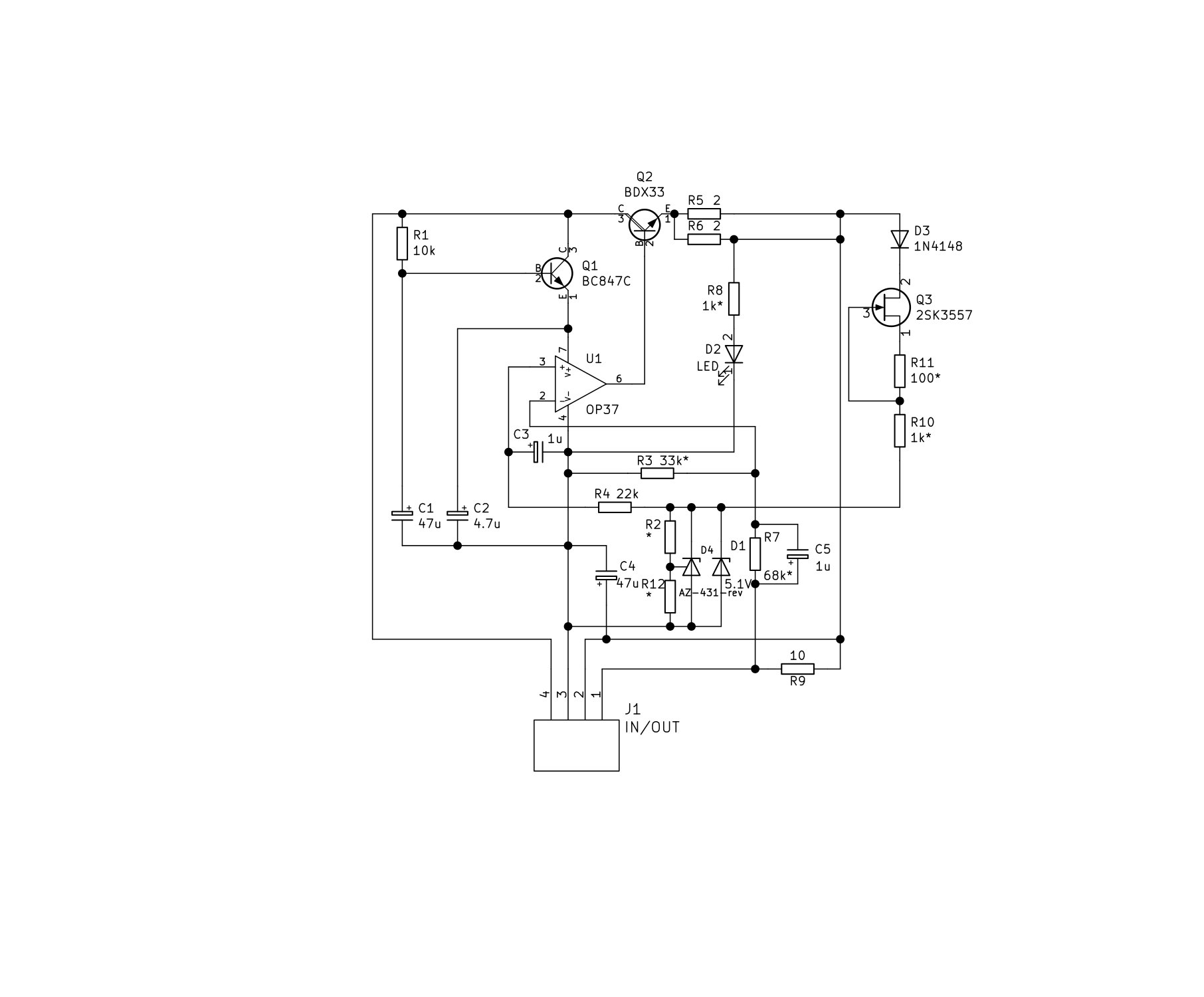
Well, I am new here. Just thinking of building a nice PSU for myself recently. The first came into my mind is σ22 on amb.org since I have been reading their designs for quite some times. But the sigma 22 uses discrete parts in the design. I don't want to play with transistor pairing and buy some expensive current diode. So after exploring the schematic, I decided to use OPAMP in the design. Then here is the design. You can find the schematic, PCB print and Gerber files in the attachment. I am not quite sure about my design. So there might be some errors. If you find any, please let me know. Thanks.
Attachments
You are right not to be sure because it's not going to work (as expected). There are several errors, mostly to do with not understanding the functions of the sub-circuits, including the OPamp (hint: can you put the inputs of the OPamp to potentials higher than it's positive power supply or lower than it's negative power supply, and in fact how close to the power supply voltages can they go and still work as expected).
Also, do not expect people to simply point out errors as this would be a case of 'here is my idea, now please someone do all the actual real world design for me'. A circuit shows a lot about the general level of understanding of the author - random errors and things overlooked aside. There is no use pointing out a problem that is a result of not understanding fundamental stuff because without that understanding you will not be able to arrive at the solution, and neither will you be able to understand the solution if someone just supplies it finished for you to use.
Also, do not expect people to simply point out errors as this would be a case of 'here is my idea, now please someone do all the actual real world design for me'. A circuit shows a lot about the general level of understanding of the author - random errors and things overlooked aside. There is no use pointing out a problem that is a result of not understanding fundamental stuff because without that understanding you will not be able to arrive at the solution, and neither will you be able to understand the solution if someone just supplies it finished for you to use.
Actually schematic should work (I mean the the positive rail).
What about the negative rail, you must put the capacitive multiplier on the negative input, symmetric to the positive rail, with a PNP transistor, of course.
And if you try a little bit harder you will come to the solution I use, see it:
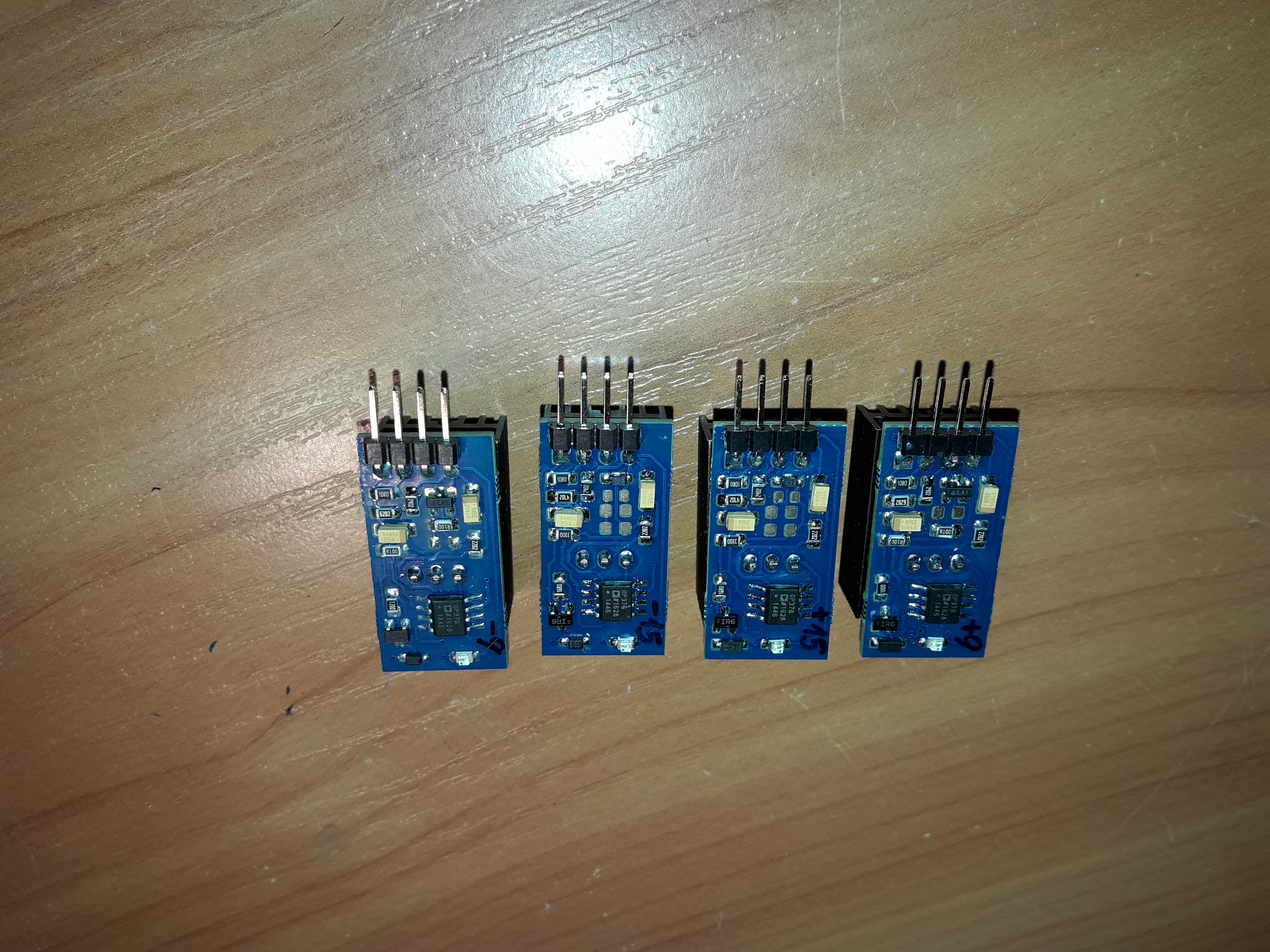
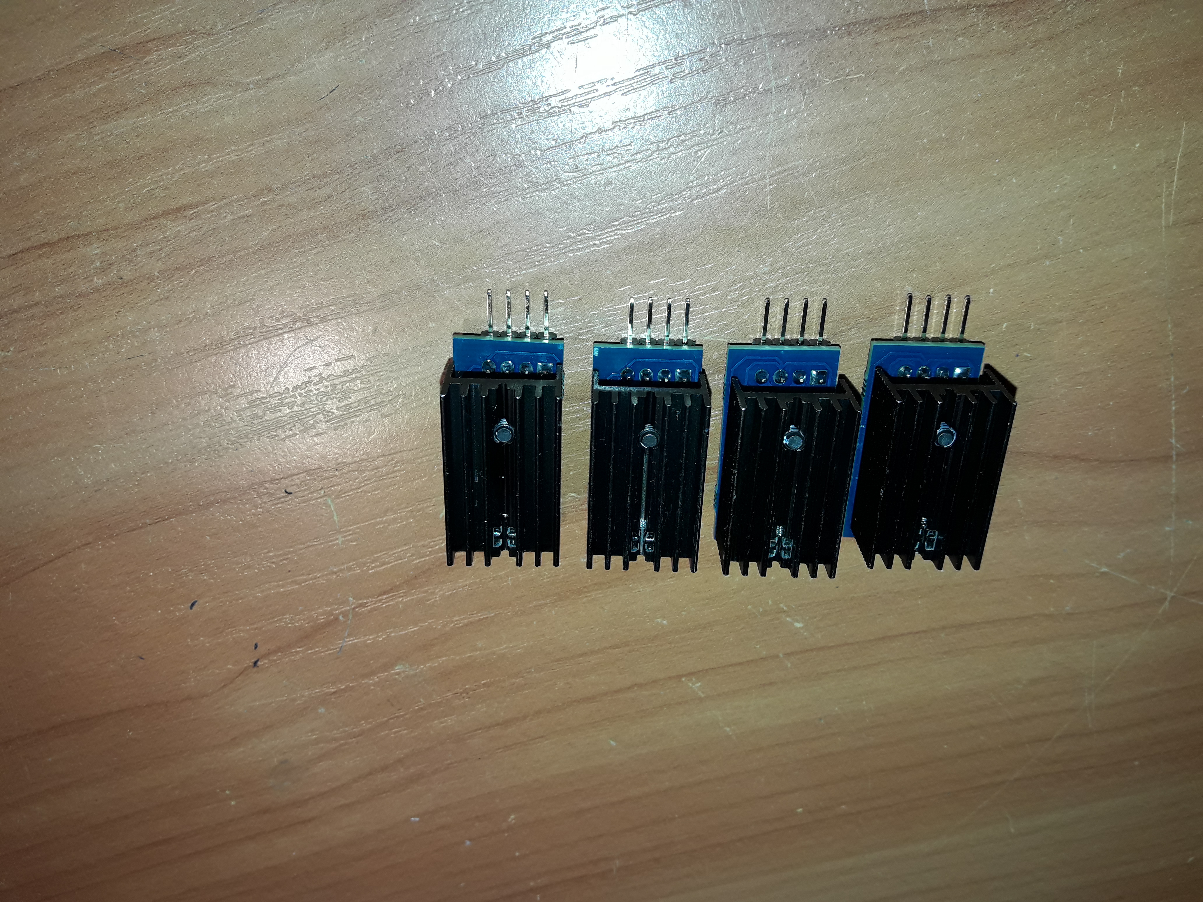
And since I see you use KiCAD like me, one advice - try to install and use its nightly builds - the software is close to its 5-th version which has a lot of improvements and new features compared to the version you use. I built these regulators using KiCAD and you can see how they look:
Regards
Alex
What about the negative rail, you must put the capacitive multiplier on the negative input, symmetric to the positive rail, with a PNP transistor, of course.
And if you try a little bit harder you will come to the solution I use, see it:
And since I see you use KiCAD like me, one advice - try to install and use its nightly builds - the software is close to its 5-th version which has a lot of improvements and new features compared to the version you use. I built these regulators using KiCAD and you can see how they look:
Regards
Alex
Yes, you're right... but in some ideal universe ") .
.
There are always some asymmetries in the OPAmps input currents which switch the process. And the OPAmps I use always work.
Of course I can name several ones which refuse to start (in a negative rail) but in such a case there is a little helper network which solves the problem.
.There are always some asymmetries in the OPAmps input currents which switch the process. And the OPAmps I use always work
.Of course I can name several ones which refuse to start (in a negative rail) but in such a case there is a little helper network which solves the problem.
- Status
- This old topic is closed. If you want to reopen this topic, contact a moderator using the "Report Post" button.