Hello everybody,
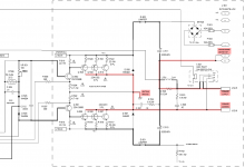
I'm looking for some information regarding an intriguing output stage used by the manufacturer QSC. They equip their power amps with a circuit which allows them to connect the output transistors directly to the grounded heat sink, without the use of any insulation inbetween. I've highlighted some connections in the schematic which have been called drawing errors in a german forum, but obviously they're not (I can tell since I own two of that amps).
What I'm actually asking for is some more information about that topology. It seems interesting to me to design a smaller amp that way, but I want to understand how the whole thing works first") . Temperature compensation is done with a 50 Ohm PTC which is not easily acquired - is there another way using transistors like in other amps?
. Temperature compensation is done with a 50 Ohm PTC which is not easily acquired - is there another way using transistors like in other amps?
I have tried a simulation run in LTspice, but it seemed that the stage is not unity gain like other o/s-es. Unfortunately I don't have enough experience to figure out how this thing does what it does, so any hints or literature would be highly appreciated!
Thanks in advance.
I'm looking for some information regarding an intriguing output stage used by the manufacturer QSC. They equip their power amps with a circuit which allows them to connect the output transistors directly to the grounded heat sink, without the use of any insulation inbetween. I've highlighted some connections in the schematic which have been called drawing errors in a german forum, but obviously they're not (I can tell since I own two of that amps).
What I'm actually asking for is some more information about that topology. It seems interesting to me to design a smaller amp that way, but I want to understand how the whole thing works first
. Temperature compensation is done with a 50 Ohm PTC which is not easily acquired - is there another way using transistors like in other amps?I have tried a simulation run in LTspice, but it seemed that the stage is not unity gain like other o/s-es. Unfortunately I don't have enough experience to figure out how this thing does what it does, so any hints or literature would be highly appreciated!
Thanks in advance.
Attachments
Its a complementary follower pair output stage, and it can have gain.
I've noticed that it looks much like a CFP, but you can't simply swap the collector outputs with ground and everything works fine. What's the deal with that?
This trick allows to eliminate insulators decreasing thermal resistance.
Obviously
. But how? It is basically a trick "à la circlotron", swapping active elements and power supplies.
A bit intriguing when you first see it, but not rocket science, and it does have many drawbacks to be balanced with the one small advantage: the need for floating supplies for each channel, the common mode capacitance of the supplies, etc. Not worthwhile, IMHO: Iso-cases are a much superior solution if you don't want to mess with isolating washers, etc.
A bit intriguing when you first see it, but not rocket science, and it does have many drawbacks to be balanced with the one small advantage: the need for floating supplies for each channel, the common mode capacitance of the supplies, etc. Not worthwhile, IMHO: Iso-cases are a much superior solution if you don't want to mess with isolating washers, etc.
(...) and it does have many drawbacks to be balanced with the one small advantage (...)
Now this is something I didn't know, but actually would like to know about
. Isn't there anybody out there who wrote an article or mentions some of the drawbacks etc. in a book?All in all, it's probably simpler to use a more standard amplifier design.
It is, but I like uncommon designs
.While there's some thermal improvement I really don't like any circuit that turns heatsinks into hot wires.. makes it another touch / shortcircuit hazzard when you happen to have tools in the vincinity.
It doesn't. The heatsink is grounded and connected to the case.
The design basically floats the power supply with the output signal.
It does not necesairly need a separate power supply that is grounded, you can filter the DC out of the floating supply lines WRT ground and get enough current for the driver stages. That saves some $, but generates heat in the filter resistors, and makes the amp rather nasty to troubleshoot when it fails as a shorted output transistor will result in one rail shortet do GND while the other will want to be twice it's normal value - basically the driver stages lose one power supply so it's difficult to troubleshoot the amp stage by stage. When a separate supply is used, it's not that different from a 'normal' amp.
There are several variations on that theme. Hafler also used one. The output stage can be built as common emitter (with gain!) or common collector (i.e. follower) - of course MOSFET versions also exist. Looking at the output stage can be a bit deceiving, what would normally look like a CFP is a follower because of the output and ground node inversion, and vice versa.
One notable problem with this design is it's floating supply, which means the amplifier also drives the capacitance between secondary and primary of the mains transformer. Normally this is not a great problem and it can even be used as a part of the zobel network, but unlike the classical implementation, the capacitance and it's influence is not necesairly predictable. In any case it's prudent to have a power transformer with an electrostatic shield for this type of circuit, and the shield needs to be grounded, so that the interwinding capacitance of the transformer at least has it's ends at predictable potential. Normally the actual magnitude of the capacitance is not a great problem, it will be on the order of a few nF at worst.
Other than the "upside down" output transistors, this grounded output bus is really not much different from "conventional" circuits.
Allow me an analogy. Imagine you built an amp on a breadboard. I mean literally built it on a wooden plank. You would make a split supply, and a push pull output stage. REmember, no chassis ground here. the output from the stage would feed one speaker terminal, and the other speaker terminal went to the power supply common. SO there is a loop, power supply, output stage, speaker.
Generally we must ground some point in that loop. Most amps ground the power supply common, which is the negative side of the speaker. The positive side of the speaker goes to the final stage out. But we could just as easily ground the amplifier final stage output, and leave the other end of the speaker conected to the power supply common. SO power supply common returns to ground through the speaker. Power common is not ground here.
SInce the power supply currents flow through the output and speaker, we have that either way. Think of the power supply - (let us say +50 and -50) - as a 100v space with common in the middle. The output transistors on either side, will conduct, dragging that power rail towards ground. If we drap +50 down to +25, then the -50 will in fact rise to -75, the 100v supply will still be 100v. WHen we do that, the mid point will also become 25v negative compared to rest position. SO a 25v pulse in the output will; drag the power rails 25v off center, and so the speaker will see 25v across itself.
WHen you see a problem amp, and the power rails are way offset, like 0 and +100 instead of +/-50, the only way that happens is if one output side is either shorted or turned on hard, in short - pun intended - not really any different from finding the output slammed over to one rail in a conventional amp. I don;t find these any harder to service than conventional designs. Just my opinion.
A quick tour down the row of output devices, check the drivers, and check for open resistors, and 90% of problems are found anyway. I have let my QSC certification lapse, since the sound company I used to provide tech support to went under some years back. They were a QSC dealer, and since then I see too little of it to justify keeping their name on my door. But in the years I did them, I found the QSC amps to work well and reliably and no more difficult to service than similar sized Yamaha power amps for example, and preferable to the Behringer products.
"All in all, it's probably simpler to use a more standard amplifier design. "
This is the most widely used amplifier type in pro sound at this time.
Crown, QSC, Behringer, Tapco, Alto, EV, Altec, etc. all use varients of this type.
Hafler, Acoustat, etc use it for hi-fi.
An ordinary dual secondary toroid will power a stereo amplifier, although a low-volt winding can make it simpler for a DIY project. Something like this will make a 200W/4Ω x2 amplifier:
http://www.antekinc.com/details.php?p=133
Last edited:
this schematic incorporates the "classic" mistake of combining the PSU charging circuit with the Audio output circuit.
The charging pulses feeding C510 & C511 must not share any common trace nor wire with the Audio side of the amplifier. They must be separated. Then connect from PSU zero/common Volts to the Main Audio Ground.
Look carefully at the length of wire connecting C510 to C511. Study it. It shows exactly what must NOT be done.
I posted a "toy" floating supply amp sim some time ago - I like viewing the principle as common emitter/source output - the CFP/compound output that lets you gnd the collector/drain of the output Q is just a detail
http://www.diyaudio.com/forums/solid-state/101602-qsc-clones-backwards-amps.html#post1205743
pro amps may expect tt drive long cables, be stable into large Cload - but for performance of the output stage lower parasitic C can be helpful - and EI split bobbin pwr xfmr have much lower pri-sec C than toroids
Last edited:
- Status
- This old topic is closed. If you want to reopen this topic, contact a moderator using the "Report Post" button.
- Home
- Amplifiers
- Solid State
- "Inverted" (not 'Inverting') Output Stage