http://classicvalve.ca/docs/MooseFET_docs_v1.pdf There is the moosefet preamp with schematic. Howabout a phase splitter much like that?
But, really most any fet based concertina / phase splitter would be interesting to try. Failing that, well, just please "anything" more interesting than yet another boring DRV134.")
But, really most any fet based concertina / phase splitter would be interesting to try. Failing that, well, just please "anything" more interesting than yet another boring DRV134.
I have to purchase and/or build several options to interview for bridging the LM1875 Triple Parallel project.
These modules need something to bridge them, and I wouldn't want anyone to get bored. Notice the current handling. These are for loud fun playback, of concerts. But more specifically, the amplifiers themselves are able to provide the feature of fore-aft depth from a monophonic speaker, but they fail to provide the matching width feature to complete the requirements of a plausible substitute for a concert.
The apparent width presented by a (each) monophonic speaker will have to be provided at the input of the amplifier. I'm hoping to find the means to bridge them that will include this missing feature, because that would be elegantly streamlined.
Research is progressing slowly, but turned up:
OP275 by Iam444
Post: http://www.diyaudio.com/forums/tubes-valves/172140-anyone-else-tried-opamp-driver.html#post2287106
Schematic:
This looks very do-able, but not necessarily better than DRV134? Opinions?
"MOSFET as a cathodyne splitter by" Miles Prower
Post: http://www.diyaudio.com/forums/tube...hase-inverter-drive-valve-pa.html#post2772587
Schematic:
This doesn't quite look ready for prime time.
OP275 by Iam444
Post: http://www.diyaudio.com/forums/tubes-valves/172140-anyone-else-tried-opamp-driver.html#post2287106
Schematic:
This looks very do-able, but not necessarily better than DRV134? Opinions?
An externally hosted image should be here but it was not working when we last tested it.
"MOSFET as a cathodyne splitter by" Miles Prower
Post: http://www.diyaudio.com/forums/tube...hase-inverter-drive-valve-pa.html#post2772587
Schematic:
This doesn't quite look ready for prime time.
Throwing my own confusion at it.
Choice of njfet not critical, any
pair that matches and conduct
up to 7mA without forward bias
on the gate.
If you tryin' to drive some toobage,
might even get a little A2 action...
Choice of njfet not critical, any
pair that matches and conduct
up to 7mA without forward bias
on the gate.
If you tryin' to drive some toobage,
might even get a little A2 action...
Attachments
Last edited:
Lazy, I'm at a loss to see how yours splits phase?
Seems like both paths to output are inverting, and
nothing to guarantee a specific gain or gain balance....
-----
OK, unity gain non-inverting. Confusing cause you
drew neg rail at the top, and abuse symbols that do
not suggest which ends might be source and drain.
Yeah yeah, I know some jfets are symmetrical.
But doesn't help clarity to draw them that way...
It still don't split...
Last edited:
No circuit from me!
You are not splitting anything, you are inverting
It is not phase, it is polarity
Beeing a tech forum we should use correct terms, I know it sounds petty and pedantic, but you would not like your doctor say: you have HepB when it is HepC, would you? E
The single input is split into two outputs.
In terms of sinusoids, inverting is equivalent to shifting phase by 180 degrees.
Close enough?
The single input is split into two outputs.
Yes exactly speaking, but Daniel wants to have also one phase to be inverted to use it for bridging amplifiers.
My sch proposal was wrongly marked with plus and minus. I am sorry it is only in phase splitter (non inverting double buffer). Here is corrected sch where are the outputs correctly marked.

Attachments
That pair of non-inverting outputs might be a splitter.
But why is useful to build one non-inverter N channel,
and the other non-inverter in P-ch? I can't imagine...
Both exactly same thing, but won't ever quite match.
This is not a phase splitter. One output has to invert,
or rotate the voltage phase 180 degrees for that....
And helpful if equal but opposite outputs present the
same impedance. At least you got that feature right...
----------
MOSFET concertina (circuit shown somewhere earlier
in this thread) fails equal impedance test if operated
open loop. As you might if bridging two amps...
Source impedance is much less than the drain.
It is interesting to note that in closed loop amps
with concertina splitter (like Williamson), the two
impedances are forced equal by the global closure.
Strange, but true...
I went to a lot of trouble to invent a concertina
with equal open loop impedance, only to discover
that my "fix" does nothing with the loop closed.
Big to-do about nothing....
Last edited:
Hybrid concertina was my folly. I got the equal impedances I was after!
But proved useless and redundant in face of global negative feedback.
Global loop equalizes plate and cathode impedance to the same effect.
You can't imagine my dissapointment...
I can do an equal impedance concertina like this with all FETs only.
A little more complicated since they do not have a natural Mu...
But would be silly, no point at all... Circuit I gave at post #8 is
far simpler way to use FETs to split phase with equal impedance.
Equal impedance only important if no greater loop will be closed
around both. But where it won't increase part count to make it so,
(as in post #8) it also doesn't hurt anything...
Attachments
Last edited:
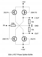
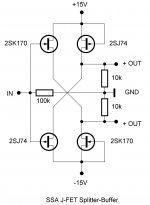
SSA J-FET Phase Splitter-Buffer
Not everyone here is smart as you are, but we are trying and learning ...
Here is simple but effective solution with all possible options at the input as well as on the output, buffers already included to drive power amp for each phase.
Regards, Andrej
And helpful if equal but opposite outputs present the
same impedance. At least you got that feature right...
Not everyone here is smart as you are, but we are trying and learning ...
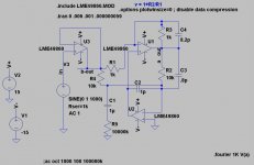
Just for fun and curiosity, is it possible to make something very much like the MooseFet IRF710, except with the major difference being phase splitter duties for bridging amplifiers?
Here is simple but effective solution with all possible options at the input as well as on the output, buffers already included to drive power amp for each phase.
Regards, Andrej
Attachments
. . .You are not splitting anything, you are inverting It is not phase, it is polarity. Beeing a tech forum we should use correct terms. . .
My apologies for incorrect terminology. I will try to use phase inverter. And, I will attempt Beeing, if it is ever necessary to harvest honey manually.
More seriously, it is my first time to build this type of amplifier. So, I may not understand some of the terminology and circuits. It is at once both ordinary and unique.
The ordinary part is that the triple parallel LM1875 is a high current op amp that doesn't contain the noisy inbuilt active limiters of modern overrun power op amp design. The unique part is avoiding the need to dash to the volume control to turn down the amp after only a few moments of exuberance.
I'd like to avoid the DRV134 for exactly the same reason that BJT front end driving Power Tubes makes the backwards sort of hybrid that sounds like a solid state amplifier. Of course it works fine, but there will be something missing along with the classic sound. The missing thing is a tube or a fet.
And, for my cost effective project, I'd rather try the fet.
Last edited:
Here is simple but effective solution with all possible options at the input as well as on the output, buffers already included to drive power amp for each phase.
Regards, Andrej
Thank you very much.
I'm sorry to ask this, but can we please avoid using an input transformer?
Last edited:
Throwing my own confusion at it.
Choice of njfet not critical, any
pair that matches and conduct
up to 7mA without forward bias
on the gate.
If you tryin' to drive some toobage,
might even get a little A2 action...
Thanks Ken!
What sort of interesting layout or additions are needed to keep the fets stable with this circuit?
I think that the triple parallel LM1875 modules would overheat and misbehave if there was a great deal of input at pitches higher than the audio band.
Last edited:
You will want 3 resistors that must connect to the MOSFET
gate to come together close enough that all act as stoppers...
You don't want a long stub of undamped wire hanging on
that MOSFET gate to resistors located far away...
I don't think the JFET follower gates need stoppers, the drains
aren't going anywhere, and the sources follow at unity. Still,
100R on those gates probably wouldn't hurt anything. And
maybe a small bypass cap to GND at each JFET drain, just
so nothing layoutwise allows those drains to wiggle..
The non-inverting output will have more bandwidth than the
inverting output. If that bugs you, there are ways to make
them more equal... You could throw individual ferrite beads
to sandbag both down to equal bandwidth. And/or common
mode choke to force them both equal and opposite... I think
this is now going a bit overboard, but you asked...
This circuit biases itself to accommodate most JFETs and
mabey some of the higher transconductance twin triodes
if you were to give the rail here a bit more voltage...
Keeping it simple and compact is probably as good or
better than making room for all this extra insurance.
Last edited:
Thank you very much.
I'm sorry to ask this, but can we please avoid using an input transformer?
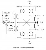
Hi Daniel,
you'd be surprised how many transformers and induction based elements are in the music production chain. And that is all before your system even starts to play the music. Let me just remind you a little: microphones (electromagnetic induction), all kinds of musical instruments pick-up's, microphone step-up/impedance matching transformers, S/PDIF input transformers, high-end TVC (transformer volume control), tube amps output transformers, just to mention some of them. MM/MC heads are considering, still, as the best musical source in a home system ...
Recently I had opportunity to listen to some high-end amplification based on transformers quality and I was impressed:
- Jeff Rowland Criterion Preamplifier (packed with Lundahl transformers)
- Jeff Rowland Model 625 Power Amplifier (Lundahl transformers on the input)
- Audio Tekne MM/MC Preamplifier ( nothing else but transformers, TVC's)
Transformer is the best AC device on the planet, it is practicaly everywhere, because we can adopt it to the specific needs. As a signal line transformer there is not easiest way to step up/down voltages, to invert the phase of the signal, balanced input/output again with transformer, also you get impedance matching plus noise rejection as a positive side product, etc.
So my Phase Splitter-Buffer proposal wasn't that bad at all, don't you think, especially if I remind myself about what you will use after this little fellow.
Regards, Andrej
Attachments
- Home
- Amplifiers
- Solid State
- Fet based phase splitter?