Maybe those Italian designers should tell us about this Ebay one here now. It will be interesting to see how stable these 4 pairs CFP are with pro. use (if they survive)
I have read (but not built) large CFP stages that are more stable because Re is kept in Emitter leads, to avoid inductance in collector leads and those connections can be short tracks. Otherwise. in regulators, you often see ferrite beads to damp oscillation there.
So you know the designers are aware of the problem with collector inductance.
The crazy thing is, most manufacturers try to solve it the same way as EF type and I don't believe it works that way. I can be wrong, too
ημμμ that can also be intersting i could look to a schematic if you have one
It is a standard, ordinary CFP structure.
Reverse darlington. The IRF610 IRF9610 driver.
There is also a standard EF output stage. It is suitable for most DIYER.
I will be his name out of L20V9。
Attachments
daviddsailor
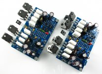
I powered up my L20 V9 boards today. Whilst testing at low power into 6 ohm resistors (about 10WRMS) I switched from sinewave (at 1kHz) to square wave. I blew both 2A protective fuse to the board. I found that one 817 and one 1047 were shorted. I took them out and used only the remaining 3 pairs. It works OK. I ordered one of each from a local supplier, cost $20AUD. Now I find I could have purchased 5 pairs for the same cost from the US!! Still I couldn't wait.
Now I have both L20 boards working I can see crossover distortion on the CRO waveform (tested to 35W so far). I would like to increase the idle current to at least 100mA. At present it is 10mA or less. Any suggestions? I probably can work it out myself but would like to know if anyone else has tried. I haven't listened to the sound yet. A project for tomorrow! Would be nice if I had a circuit. The V9 uses a mosfet driver. The circuit I have is for an earlier version.
L20 amplifier
The supplier of the amp boards gave me a circuit which turned out to be an earlier version. I tried again and received a circuit which has the mosfet driver but only shows the front end as labelled boxes. I have assumed that if I cut and paste the circuits I might end up with the correct one for the V9, but somehow I don't think I will ever trust it unless I trace everything out. The designer of the L20 hasn't responded to requests for the circuit. There seem to be more V's of the L20 than I've had hot breakfasts and I find the whole issue quite frustrating (as one who likes things simple!).
The supplier of the amp boards gave me a circuit which turned out to be an earlier version. I tried again and received a circuit which has the mosfet driver but only shows the front end as labelled boxes. I have assumed that if I cut and paste the circuits I might end up with the correct one for the V9, but somehow I don't think I will ever trust it unless I trace everything out. The designer of the L20 hasn't responded to requests for the circuit. There seem to be more V's of the L20 than I've had hot breakfasts and I find the whole issue quite frustrating (as one who likes things simple!).
L20 Amplifier
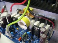
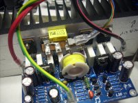
My Ebay power supply boards arrived recently. Fitted with suspicious looking Nippon Chemicon 80V 10,000uf electros type KMG code A7088. I can't find any NC 10,000uf KMG types in NC current datasheets. Recent production KMG types are radial lead in much smaller values, not snap in types. Am I being paranoid about these caps? Do they fit the "bad caps" mold? Comments ...
My Ebay power supply boards arrived recently. Fitted with suspicious looking Nippon Chemicon 80V 10,000uf electros type KMG code A7088. I can't find any NC 10,000uf KMG types in NC current datasheets. Recent production KMG types are radial lead in much smaller values, not snap in types. Am I being paranoid about these caps? Do they fit the "bad caps" mold? Comments ...
It is a standard, ordinary CFP structure.
Reverse darlington. The IRF610 IRF9610 driver.
There is also a standard EF output stage. It is suitable for most DIYER.
I will be his name out of L20V9。
I wonder why the schematic for this amp is not being disclosured. Particularly if there seems to be several versions of it.
Diygeek has already held off on his potential purchase, and there will be many others that will do so.
I am involved on another thread over the Diamond Differential kit sold by Jim's Audio and Tubeshunter, and from what I see the only reliable eBay kits seem to be those involving 3886 chips.
OTOS I think discrete amps can be tweaked better, and this discussions should help people that are looking for discrete affordable kits on eBay that DO WORK AS THEY SHOULD!
Why don't we start here in doing so?
Carlos
L20
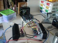
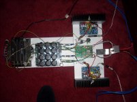
I got back to the L20 boards again yesterday. I replaced what was left of the output devices on my blown up board with 4 pairs of new devices. Everything worked OK initially except that they have a rising frequency response with twice the voltage out at 100kHz than at 1kHz (my generator doesn't go any higher). I tested both boards to 40WRMS into 6 ohms then I noticed both amps getting very hot without any input. One in fact had blown the 2A protection fuses. So I guess they went into HF oscillation even though I didn't see it on the CRO. Unless I'm doing something radically wrong, these boards are hotter that a two bob watch. Today I will put an inductive LPF on the outputs and see what blows up next!
I got back to the L20 boards again yesterday. I replaced what was left of the output devices on my blown up board with 4 pairs of new devices. Everything worked OK initially except that they have a rising frequency response with twice the voltage out at 100kHz than at 1kHz (my generator doesn't go any higher). I tested both boards to 40WRMS into 6 ohms then I noticed both amps getting very hot without any input. One in fact had blown the 2A protection fuses. So I guess they went into HF oscillation even though I didn't see it on the CRO. Unless I'm doing something radically wrong, these boards are hotter that a two bob watch. Today I will put an inductive LPF on the outputs and see what blows up next!
Attachments
It's obvious these guys are not going to send or post a schematic, they are just making excuses and hedging their bets.
I learned my lesson from ordering an L7 without any documentation,just a bag of parts. Tried to get a schematic to no avail. Plus long shipping times
Never again will I order another Chinese amp kit, not worth the hassle and you can never trust the components.
If most of us stopped buying these kits without documentation they might get the message and do a better job.
Maybe the Moderators need to take a closer look at these guys.
If they didn't sell so cheap, they would be able to spend the necessary time to do the documentation correctly and properly, in English.
There will always be a demand for the cheap product while this sort of shoddy outcome is tolerated. Unfortunately you do nearly always get what you paid for.
Hugh
There will always be a demand for the cheap product while this sort of shoddy outcome is tolerated. Unfortunately you do nearly always get what you paid for.
Hugh
I have some experience up at this power level, and if you obey the engineering guidelines, no class AB 250 watter is going to fit on a board the size indicated by the thread starter. If you bias up into class B, remove any form of protection, and are happy with sub-optimal slew rates and distortion, then you may get it. But, it aint hi-fi.
A 200W hi fi amp that can drive any reasonable hi speaker takes a lot of effort to design and build properly.
The best advice is to build something that's well documented and can be vouched for by other forum members (take a look at OStrippers designs), or buy a decent kit (AKSA). There's also the great Leach amp. Be prepapred to put quite some effort into the heatsinking as well. Class AB with .33 Ohm output degen resistors will need 78mA per pair - so for 4 pairs on 65V rails you are looking at an idle dissipation of 40W, and if you expect it to deliver 200W for any length of time, you should figure on heatsinks that will disspate 120-150W with typical speaker loads.
Now you know why decent 200-250W class AB commercial amps are so big and heavy and cost a lot . . .
;-)
Last edited:
L20 V9
I finally tamed the L20 boards today. I fitted LPF's to each output and that put an end to the boards going into oscillation. I ran them both for about 5 minutes at 50WRMS but had to drop the power as the heat sinks got too hot. The dummy loads were sweating a bit too. I reconfigured the Cat 6 wiring I was using to connect from the amps to the dummy loads and this got rid of the rising frequency response and the overshoot on a 1kHz square way test signal. There is basically no DC offset on one amp and about 10mV on the other. There is some visible cross over distortion on a sine wave test signal and this may reduce if I can get the idle current up. At present each amp only draws about 3mA total at idle which seems to be far too low. All I have to do now is put together a speaker protection board and I can have a listen.
I finally tamed the L20 boards today. I fitted LPF's to each output and that put an end to the boards going into oscillation. I ran them both for about 5 minutes at 50WRMS but had to drop the power as the heat sinks got too hot. The dummy loads were sweating a bit too. I reconfigured the Cat 6 wiring I was using to connect from the amps to the dummy loads and this got rid of the rising frequency response and the overshoot on a 1kHz square way test signal. There is basically no DC offset on one amp and about 10mV on the other. There is some visible cross over distortion on a sine wave test signal and this may reduce if I can get the idle current up. At present each amp only draws about 3mA total at idle which seems to be far too low. All I have to do now is put together a speaker protection board and I can have a listen.
Attachments
L20 V9
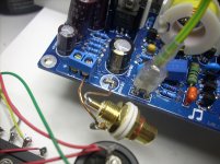
The Eagle has landed! I'm finally listening to the L20 V9 amp. It really sounds VERY good, especially since I removed the crummy RCA input cable and took my interconnect almost directly into the L20 board. There is some hum/buzz with my ear in the midrange driver but only when there is an input connected. Not so much a hum loop as direct radiation from the transformer/rectifiers. There is ony 3mA of idle current on each rail and some visible crossover distortion Any suggestions on how to increase the idle? I'd rather not experiment in case I blow it up (again).
The Eagle has landed! I'm finally listening to the L20 V9 amp. It really sounds VERY good, especially since I removed the crummy RCA input cable and took my interconnect almost directly into the L20 board. There is some hum/buzz with my ear in the midrange driver but only when there is an input connected. Not so much a hum loop as direct radiation from the transformer/rectifiers. There is ony 3mA of idle current on each rail and some visible crossover distortion Any suggestions on how to increase the idle? I'd rather not experiment in case I blow it up (again).
Attachments
L20 V9
I obtained a further significant improvement in the sound by wiring an RCA socket directly to the input terminals and an even greater improvement when I wired the socket directly to the amplifier side of the input coupling capacitor (no DC from my source). Various previous L20 versions seem to have a small electrolytic as an input cap but my L20's came with a surface mount (stacked something or other) and it sounds terrible compared with the direct connection. Next trick is to wire up the 500VA toroids and see what +/-70V can do!
I obtained a further significant improvement in the sound by wiring an RCA socket directly to the input terminals and an even greater improvement when I wired the socket directly to the amplifier side of the input coupling capacitor (no DC from my source). Various previous L20 versions seem to have a small electrolytic as an input cap but my L20's came with a surface mount (stacked something or other) and it sounds terrible compared with the direct connection. Next trick is to wire up the 500VA toroids and see what +/-70V can do!
Attachments
As Bonsai has already posted, you are going to need significant bias current to get MOSFETs sounding good. The figure of 78 mA per pair may even be conservative, since the actual figure is quite rubbery. It's difficult to imagine how the sniff of just the few mA you mention, spread over four output pairs in class AB could be called bias. There is also the current flowing in the VAS (say 12 mA) and the input stage (say 3 mA) That's 15 mA without the output stage or any bias. I would think the measurement technique through, as something is wrong there. If the bias adjustment is actually fixed by the use of simple resistors to set it, there is obviously something quite wrong there too.
Surely, there is some adjustment for total bias current so it can be set to around the appropriate figure of about 360 mA. Yes, it's gonna get warm and with the higher rail voltages, very warm unless the heatsinks are quite generous. I would estimate sinks for 300W/4R to be better than 0.2 degrees C/Watt rated for each channel. In case you aren't aware, that's almost twice the size of the largest Conrad heatsink available here retail.
Don't try this amp with 70V rails on 4R loads at high power. It may limit itself but likely just wont survive on a stiff supply like the 500VA toroid.
Another concern is using a direct input connection with no DC isolation other than (hopefully) that which might be in the input source device. Frankly, I'm amazed you find the audio improved when the major crossover distortion problem at the amplifier output stage would obscure normal perception of audio quality. The capacitor supplied must have been sorely defective to be so obvious.
I imagine the heatsink is quite cold idling, but would you like to tell us what voltage (mV) you read across any of the 0R33 resistors?
Last edited:
L20 V9
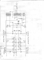
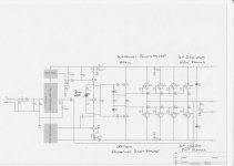
OK, you guys are forcing me to do some head scratching, so here goes. The L20 V9 doesn't use mosfets in the output stages. It uses 2SD1047/2SB817 which are NPN/PNP planar silicons, 4 pairs. It uses a mosfet driver pair, IRF610/IRF9610 N-channel/P-channel. As supplied there is no adjustment for bias but I have put in a pot (shown on the attached schematic). As for my measurement of the current, I used a current clamp DC ammeter on both the +ve supply line and the -ve line. I got about 3mA on each. I managed to bias it up using the pot and thought that 100mA total might be a good number but naturally I blew up the amp (as per usual). Next time I took it to about 40mA total and as it heated up the temp compensation must have kicked in and the total current dropped to about 10mA. I then tweaked it a bit more and I think it is at about 20mA at present. As for the heatsink, 'IF' I was going to run them anywhere near full power I would use Conrad MF35-151.5 heatsinks which are good for 0.21C/Watt. I don't know if there is visible crossover distortion since I biased the output stages up a bit because I was so eager to listen that I did not put the CRO on it. But to my old ears it does not have any audible distortion. Believe me, the sound quality improved out of sight when I bypassed the input cap. When I find a good sounding cap I will put it in. The heatsink only gets slightly warm at any stage and as for the drop across the 0.22Ohm resistors, I haven't measured it yet. Sorry about the crappy sideways schematic. To be continued.
OK, you guys are forcing me to do some head scratching, so here goes. The L20 V9 doesn't use mosfets in the output stages. It uses 2SD1047/2SB817 which are NPN/PNP planar silicons, 4 pairs. It uses a mosfet driver pair, IRF610/IRF9610 N-channel/P-channel. As supplied there is no adjustment for bias but I have put in a pot (shown on the attached schematic). As for my measurement of the current, I used a current clamp DC ammeter on both the +ve supply line and the -ve line. I got about 3mA on each. I managed to bias it up using the pot and thought that 100mA total might be a good number but naturally I blew up the amp (as per usual). Next time I took it to about 40mA total and as it heated up the temp compensation must have kicked in and the total current dropped to about 10mA. I then tweaked it a bit more and I think it is at about 20mA at present. As for the heatsink, 'IF' I was going to run them anywhere near full power I would use Conrad MF35-151.5 heatsinks which are good for 0.21C/Watt. I don't know if there is visible crossover distortion since I biased the output stages up a bit because I was so eager to listen that I did not put the CRO on it. But to my old ears it does not have any audible distortion. Believe me, the sound quality improved out of sight when I bypassed the input cap. When I find a good sounding cap I will put it in. The heatsink only gets slightly warm at any stage and as for the drop across the 0.22Ohm resistors, I haven't measured it yet. Sorry about the crappy sideways schematic. To be continued.
Attachments
 Ah, the light shines - it is not MOSFET so bias can be much lower. Apologies for the confusion but I'm not the first here to assume it was.
I think you will be led a merry chase expecting accuracy from a clamp meter at low DC current. Others may have a better appraisal but I would be sceptical, particularly in close packed circuits. For reliable readings, it's not difficult to measure the voltage across suitable resistors in the circuit, given that readings will be limited to the resistor+meter accuracies but you can expect ~3% across those Re resistors. A quick calc. in the head and it's done. You can then cross-check the reedings this way.
Let's see the real figures which, for ~25 mA/pair, should be 100 mA total, read as 0.22 * 0.025 = 0.0055 or 5.5 mV across each emitter resistor of the output pairs. For a little better chance of accuracy, read across both resistors in the pair, from emitter to emitter and expect ~11 mV with the same nominal 25 mA bias. Rest assured, if the sinks are getting warm with modest audio levels, the bias will be much more than 3 mA total. With typical setting, you might expect a total of 120 mA current drawn by each idle amplifier.
A standard 300 mm Conrad sink rated 0.37 Deg. C/W should be adequate, as the SC studio 350 uses it. The only problem being the close packing of transistors and local overheating. This is not good. BTW, I think a pot. is shown in the conventional position, in the base circuit of the bias generator transistor. There is some note there too but I can't make it out. Perhaps it specifies a fixed resistor in lieu?
L20 V9
I have scanned the schematic again and it looks a bit better. I also fathomed out how to rotate it. The clamp meter I am using is of professional quality and I have no reason to doubt it as it has agreed with other measuring methods in the past. Still, I will now measure the voltage across the 0.22 Ohm resistors as I have always done with other amps. I was wary of poking the meter leads into this PCB in light of it's previous liking for 'taking off'. The pot shown in the circuit is one I put in. I used 500 Ohms at first but changed to 5K when I didn't get much response from 500. Also, now I look at the circuit in more detail I see that there is some protection against HF signals (or have I got that wrong too?) in the form of a 10 Ohm resistor and 0.1uf cap to ground on the output. This would represent (?) a 170 ohm load at 10kHz and 26 ohm load at 100K. I suppose it could be construed as being there to stop stuff getting back in from the speaker wires as much as loading the amp. I will have to get Mr. Selfs' book out again and have a look. If the amp went into oscillation I suppose it would make mincemeat of the 10 Ohm resistor and maybe it has. Regards.
I have scanned the schematic again and it looks a bit better. I also fathomed out how to rotate it.
The clamp meter I am using is of professional quality and I have no reason to doubt it as it has agreed with other measuring methods in the past. Still, I will now measure the voltage across the 0.22 Ohm resistors as I have always done with other amps. I was wary of poking the meter leads into this PCB in light of it's previous liking for 'taking off'. The pot shown in the circuit is one I put in. I used 500 Ohms at first but changed to 5K when I didn't get much response from 500. Also, now I look at the circuit in more detail I see that there is some protection against HF signals (or have I got that wrong too?) in the form of a 10 Ohm resistor and 0.1uf cap to ground on the output. This would represent (?) a 170 ohm load at 10kHz and 26 ohm load at 100K. I suppose it could be construed as being there to stop stuff getting back in from the speaker wires as much as loading the amp. I will have to get Mr. Selfs' book out again and have a look. If the amp went into oscillation I suppose it would make mincemeat of the 10 Ohm resistor and maybe it has. Regards.Attachments
- Home
- Amplifiers
- Solid State
- L20 V8