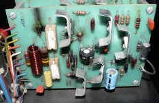
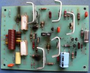
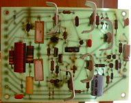
Oooops. Well the result is obvious  but I'm a bit stuck here. Firstly I don't have a service manual/circuit diagram to refer to and secondly (just as important and maybe more so) I don't know what caused the kaboom. I'm not tech savvy enough to look at the board and figure out where the problem originated but I know there are members here who can pull rabbits out of hats so I'd really appreciate your advice / suggestions. It's an opportunity to upgrade the components now that I'm repairing the amp (Audire 2) and all suggestions on improved components would be very welcome. Please remember I'm pretty new at this so if you can spare the time to download the photo and maybe put arrows on it with "here" and "here" kind of thing that's be especially great.
FWIW I do like the older Audire power amps - apart from being the only ones I can afford they have a sweet sound and are built like the proverbial you-know-what. But hey, even a Levinson / Krell / Rolls Royce can break down and this is one old amp that deserves a rebuild and some DIYaudio TLC.
Thanks, Mike.
but I'm a bit stuck here. Firstly I don't have a service manual/circuit diagram to refer to and secondly (just as important and maybe more so) I don't know what caused the kaboom. I'm not tech savvy enough to look at the board and figure out where the problem originated but I know there are members here who can pull rabbits out of hats so I'd really appreciate your advice / suggestions. It's an opportunity to upgrade the components now that I'm repairing the amp (Audire 2) and all suggestions on improved components would be very welcome. Please remember I'm pretty new at this so if you can spare the time to download the photo and maybe put arrows on it with "here" and "here" kind of thing that's be especially great. FWIW I do like the older Audire power amps - apart from being the only ones I can afford they have a sweet sound and are built like the proverbial you-know-what. But hey, even a Levinson / Krell / Rolls Royce can break down and this is one old amp that deserves a rebuild and some DIYaudio TLC.
Thanks, Mike.
Attachments
Set a digital multimeter if you have one to the diode measurement setting and check all transistors, in one direction you should get around 400-500 on the display and the other you should get open circuit.
If all some or combinations show dead short, you have found some broken transistors.
If all some or combinations show dead short, you have found some broken transistors.
First off thank you Tekko. I do have and know how to use a DMM and VOM and can troubleshoot to a decent level. What I'm not good at (yet) is translating a board into a schematic and from that experience and 'know-how' understanding just where the functioning circuit broke down. As you can see roughly one half of the board was not affected and all the fried components are on the other half .. but I just don't have the technical experience to be able to say, "ah, yes, it probably started there when xyz failed".
Thanks too to a.wayne: the problem is it just happened after being taken out of (dry) storage: it was correctly wired (short speaker cables etc.) with all connects double checked before firing up (no pun intended - I'm a bit fastidious about things) and then it just when poof. I know the circuit has about as much protection as a paper hat in a thunderstorm but I always thought that maybe that circuit topology worked so well because of that fact - i.e. not being laden down with obtrusive to sonics protection circuits. But then again, I am a newbie at all this.
I can replace all the burned out parts when I can ID them all (no schematic or facts available at this time) but since I'm going to rebuild the board I thought it a good opportunity to use in the appropriate places in the signal path those comonents that have improved sonic characteristics over those used way back when the amp was manufactured. 1% R's here and an 'xyz' cap there sort of thing .. or am I thinking wrong here?
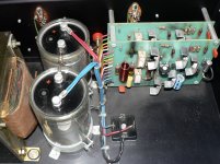
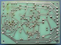
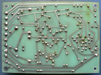
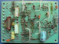
I'll strip out the board and take a photo with back-lighting to show the tracks in relation to the components - just hoping I guess that some member had prior experience with this particualr amp. BTW all resistors look to me like 5% standard old school types and the caps are probably at the end of their service life by now anyway. Fortunately the huge and expensive PSU smoothers look to be in good shape.
Best to all, Mike.
Thanks too to a.wayne: the problem is it just happened after being taken out of (dry) storage: it was correctly wired (short speaker cables etc.) with all connects double checked before firing up (no pun intended - I'm a bit fastidious about things) and then it just when poof. I know the circuit has about as much protection as a paper hat in a thunderstorm
but I always thought that maybe that circuit topology worked so well because of that fact - i.e. not being laden down with obtrusive to sonics protection circuits. But then again, I am a newbie at all this.I can replace all the burned out parts when I can ID them all (no schematic or facts available at this time) but since I'm going to rebuild the board I thought it a good opportunity to use in the appropriate places in the signal path those comonents that have improved sonic characteristics over those used way back when the amp was manufactured. 1% R's here and an 'xyz' cap there sort of thing .. or am I thinking wrong here?
I'll strip out the board and take a photo with back-lighting to show the tracks in relation to the components - just hoping I guess that some member had prior experience with this particualr amp. BTW all resistors look to me like 5% standard old school types and the caps are probably at the end of their service life by now anyway. Fortunately the huge and expensive PSU smoothers look to be in good shape.
Best to all, Mike.
Last edited:
I have a Quatre on the bench right now and it looks a lot like the Audire, the chassis and layout anyway. Could you please tell me what output transistors are in your amp? Everything looks the same, the same power xfmr, even the color of the wires in the power supply and to the PCBs.
Craig
Craig
Last edited:
.... Just a few things
first the unit will need a serious recaping
then you might as well check if the cheap carbon resistors are drifted from original value ( can happen )
then i seems that the blown resistor belongs to the base of one of the outputs in this case expect both outs and drivers are to be gone ....
a few tips
*your remark on less protection is cleaner sound is correct
*often one thing that will take you to kaboom is the bases ( mounting kit ) of the output transistors they often get loose in the pin area not the screw
* it seems that the amplifier has no thermal compensation ( if it was mine obviously and surely i would change that )
*Practice have shown that in long run amplifiers that have vertical pcb's and no ventilation fail more often since pcb's cannot dissipate heat resulting soldering issues ( something that easily can be changed in your case )
* one thing that we don't do now days is to run cables from PCB to output transistors modern transistors are accommodated on the PCB since you don't have any other option but cables the only thing that you don't do is to twist B-C-E together that it shelf can be a number one issue to take you to heavy oscillation. keep some distance between the cables
* finally and in this scheme of amplifier an open trimmer ( or dirty ) may take you to kaboom if a safety resistor is not fitted to avoid this ( the amp looks too simple to have this function also )
that's about it i actually looked for a schematic and it doesn't seem to be possible to find .. if you can hand draw one that is correct many will give you some extra help except the above
kind regards sakis
Hello Sakis and many many thanks for your input - I'm very grateful for your taking the time to advise and help me.
I understand everything you have said. It does look (as you said) as if the circuit has just about zero protection against both internal component faults and external "circuit" components. I've just removed the bad circuit board (hoping the other isn't bad but .. ?) and am taking a photograph to upload. I hope from that and the subsequent amateurish sketch that I post will be of value in deciding what to do next - apart from making the obvious replacements.
Being an "oldie" I have just about always soldered direct to pins, be it IC's or whatever I've never found sockets to be of value in doing a final assembly - just okay for testing / evaluating purposes.
In radio circuits I always placed a fixed resistor in series with a variable just in case .. I thought this was always done but I live and learn - which is of course why I'm here at DIYaudio
Once again my gratitude for your help and I hope that the pics lead to further information and advice. My best regards, Mike.
I understand everything you have said. It does look (as you said) as if the circuit has just about zero protection against both internal component faults and external "circuit" components. I've just removed the bad circuit board (hoping the other isn't bad but .. ?) and am taking a photograph to upload. I hope from that and the subsequent amateurish sketch that I post will be of value in deciding what to do next - apart from making the obvious replacements.
*often one thing that will take you to kaboom is the bases ( mounting kit ) of the output transistors they often get loose in the pin area not the screw
Being an "oldie" I have just about always soldered direct to pins, be it IC's or whatever I've never found sockets to be of value in doing a final assembly - just okay for testing / evaluating purposes.
* finally and in this scheme of amplifier an open trimmer ( or dirty ) may take you to kaboom if a safety resistor is not fitted to avoid this ( the amp looks too simple to have this function also )
In radio circuits I always placed a fixed resistor in series with a variable just in case .. I thought this was always done but I live and learn - which is of course why I'm here at DIYaudio
Once again my gratitude for your help and I hope that the pics lead to further information and advice. My best regards, Mike.
Currently the amp is using MPS U57 and MPS U07 which I'll replace. I know these are slow transistors and really old: I wouldn't mind using faster >5MHz transistors but I'm concerned about the possibility of oscillation with faster transistors. I've seen various types suggested but (as usual) what works best in one circuit isn't necessarily best for another - and I'm just not tech-savvy enough by a long way to read this circuit and know what would be suitable replacements. Can someone please advise me. Many thanks, Mike.
BTW does anyone know if the Audire Forte amps are of a greatly different design to the Audire 2? More reliable ... better more protected circuitry in either BJT or MOSFET dress. Thanks.
BTW does anyone know if the Audire Forte amps are of a greatly different design to the Audire 2? More reliable ... better more protected circuitry in either BJT or MOSFET dress. Thanks.
Last edited:
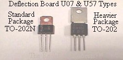
Hi. Well according to the site they are MPS U57 and MPS U07 : am I reading it wrong - they're a ways down the list - and I could be.
TheRealBobRoberts - Coin-op Parts
TheRealBobRoberts - Coin-op Parts
Attachments
Last edited:
Hey that would be fine if you don't mind - of course at due recompense. I can't do anything with it over the weekend, well not much on the Audire project anyway, but that'll be good news for the ancient Tandberg TCD 310 cassette I'm refurbishing. I think the previous owner lived in an eqitorial swamp ... and I do mean IN it It's unbelievable how badly some people can treat good gear isn't it. Thank God for DeOxit and toothbrushes !!
It's unbelievable how badly some people can treat good gear isn't it. Thank God for DeOxit and toothbrushes !!MPSW06 and 56 generally will run at 100V
Thanks. I'd like to keep the same case (and pinout) and I believe these are different - I'd really like to keep the amp as original as possible. Best regards, Mike.
BTW I fired it up with one board and I'm pleased to say that board is fine ... the soundstage wasn't too good though
The Tandberg says HI to everyone. Phew, anyone need a couple of pounds of verdigris !!
Last edited:
- Status
- This old topic is closed. If you want to reopen this topic, contact a moderator using the "Report Post" button.
- Home
- Amplifiers
- Solid State
- Audire ... Oh Dear !!