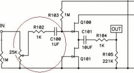
In the following circuit the 1st series capacitor has, due to some circuit impedance, a high pass response(or turnover or cutoff frequency).
Trying to determine that cutoff frequency, I've become unsure if the potentiometer, when turned, itself varies the impedance and therefore the cutoff frequency.
Anybody know for sure what the cutoff frequency(and impedance) should be for this circuit, or is fc dependant upon the setting of the pot?
Thanks.
-Chas
p.s. I asked in another forum, but couldn't get a straight (i.e. understandable)answer.
Attachments
Michael Bean wrote:
Yes, please.
The reason is I have a smaller(very high quality)capacitor I was planning on using in place of the 1uF cap at C100.
What would the cutoff frequency be for, say, a 0.1uf cap used here?
And how much would that Fc change over a 0-12kOhm range of the pot?
TIA
-Chas
Fc will be under 1 Hz at any pot setting...Could be calculated more precisely if you want to split hairs.
Yes, please.
The reason is I have a smaller(very high quality)capacitor I was planning on using in place of the 1uF cap at C100.
What would the cutoff frequency be for, say, a 0.1uf cap used here?
And how much would that Fc change over a 0-12kOhm range of the pot?
TIA
-Chas
With the pot at full volume (and assuming the device connected to the input has a zero output impedance, which in practical terms it almost surely does), it has zero ohms impedance, its minimum. At halfway, it has 12.5k in parallel with 12.5k, or 6.25k impedance. This adds to the 1M of R103 and the 1k of R102 to give a total series resistance of 1.00725 megohms. At full volume this total series resistance is 1.001 megohms. The change in cutoff frequency is less that 1 percent over the full range of the volume control.
The cutoff with a 0.1uF capacitor would be ten times higher than with a 1uF capacitor. Since the cutoff frequency is based on the product of R and C, this scenario will also change it less than 1 percent.
The -3dB point of the rolloff will be at the frequency where the capacitive reactance is equal to the resistance:
Xc = 1/(2 x PI x F x C)
1000000 = 1 / (6.28 x F x 0.1uF)
F = 1 / (6.28 * 0.1) - 1/0.628 = 1.59 Hz
A 0.1 uF is fine here, and the 1 uF is overkill.
Not sure if this is what you mean (as everyone is talking about LF cut off) but the setting of the pot and the input capacitance of the circuit does effect the HF roll off but with a 25k pot and a typical junction capacitance of a small signal FET it will be in the RF range so no worries as far as audio goes.
The question is : can the 1uF be changed.
Answer : yes.
The high pass filter of the CR is determined by the 1uF and the following resistance/impedance to ground.
The only impedances to ground are the input impedance of the jFET (~1G) and the bias resistor 1M.
The HP filter created by these is ~1u*1M i.e. RC time constant ~ 1second.
This could be reduced by ~ a factor of 10 with little effect on the sound signal coming from the speaker. If reduced by a factor of 100 then expect this to be quite audible at the speaker.
In my view this 1uF could be reduced to 100nF or 220nF and neither of these values may have an influence on the final bass response. Try it and listen.
The pot has a variable output impedance.
Depending on how the circuit, around the input & pot & source, is arranged you will find that an unbuffered pot will affect the filter frequencies operating at the input to the amplifier.
There are usually two filters at each input to be considered. A low pass filter that attenuates RF well or badly, a high pass filter that attenuates sub-sonics well or badly and also Blocks DC from entering the stage.
These inputs are at the power amp input, the attenuator input and the source input. Often the cables that connect these together must be taken into account to determine the filtering effects.
For the circuit shown the attenuator input can only be of use if the source is connected. As pointed out by Ben this can be very low <10r but it can be as high as 1k for a competently designed SS source.
The source output impedance affects the attenuator output impedance.
Output impedance of the attenuator for the circuit shown and assuming a 80r source impedance is connected will be:
25k+[80r//1M]/4 when the pot is set to half resistance (~-6dB),
or ~ 80r//1M when set to maximum resistance (-0dB),
or 0r0//[25k+(80r//1M)].
These are -0dB ~80r, -6dB ~6k3, -120dB ~0r01.
The power amp input sees these various source impedances in parallel with the cable impedances and parasitic capacitances around the input.
As Mooly said the RF attenuator is determined by the source impedance & the following Capacitance to signal ground. But no RF attenuating capacitor is shown. There is theoretically no RF attenuation. In practice there are capacitances around that will create a low pass. This input is badly designed, and yes I realise it looks like a Pass design.
I have not checked the formulae, nor the answers yet. They were all done in my head as I typed. I will correct if necessary.
Finally,
in answer to everyone questioning my right to criticise a Pass design.
I would add a few pF at the input socket, and add a few hundred pF from the (to be split) 1k series resistor.
These two caps will introduce a passive RF filter that can be tailored by the listener/user/builder/designer to give the balance between HF pass band and RF attenuation.
Last edited:
- Status
- This old topic is closed. If you want to reopen this topic, contact a moderator using the "Report Post" button.
- Home
- Amplifiers
- Solid State
- Does Potentiometer affect cutoff frequency