Hi Titinus,
I did checkout a few devices but these ones showed a superior performance")
best sound is priority ofcourse
whatever gives the result
and they look better too
only moderate classAB
no problem
some say metal house small signal devices sound better too
others will probably say its a rubbish myth
did you do the checkout by building/listening, simulation, or specsheet ?
just curious
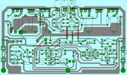
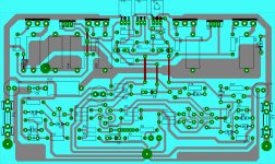
pcb for symef
i have used different casing for the output transistor.goodluck to your amp.
cheers,
joel
Volunteer needed to do the pcb.
i have used different casing for the output transistor.goodluck to your amp.
cheers,
joel
Attachments
the two outside faces of metal angles are generally pretty near flat..........
but they will need 90degr angled alu profile
which will never be a smooth fit to heatsink
heat transfer will be compromised
If there is excessive bowing then being the outside faces access to modify machine them is easy.
Thanks for the PCB Joel,i have used different casing for the output transistor.goodluck to your amp.
cheers,
joel
You v done the Bias and the output network slightly differently.
I do hope you enjoy what you hear. Keep thread up to date with your progress. I am targeting at-least 30k builders. Then we will go world wide
did you do the checkout by building/listening, simulation, or specsheet ?
just curious
I am using a formula that will be published soon. This formula has a very high level of accuracy. That is why I am giving these schematics to the diyaudio community as references to good sound. If the formula is wrong well I will have feedback from the diyaudio community, then we can use the feedback to improve the product. I am hoping to demo the products at at-least one of next years audio events.
I am using a formula that will be published soon.
ah, the secret formula
yeah, we have the needed skilled builders and designers to build very good amps
I'm sure the formula will work very well here
ah, the secret formula
yeah, we have the needed skilled builders and designers to build very good amps
I'm sure the formula will work very well here
I am sure that you can be less vague and give some objective away with regard to the formula. I think throwing you overboard may be necessary after all. OR you can share my ugly women in the dark. Now which would it be?
He he he he....outbid the publisher
I have skimmed again through Sloan pages 41 to 42, Burning amplifier, Cordell pages 9,10 and 117-210, Self Chapter 8 and I am still not sure whether a resistive load is not enough.
I agree we need a reserve of 3times the current for the speaker in relation to a resistor of the same impedance for some program material. With this in mind then, the amplifier is better suited for 100Watts 4 Ohms.
bias generator
i notice that also and read your note below the schematic.anyway it will be easy to edit sorry for that im just an enthusiast and not a designer and prone to mistakes.hope that you will post again the final schematic.
Thanks for the PCB Joel,
You v done the Bias and the output network slightly differently.
I do hope you enjoy what you hear. Keep thread up to date with your progress. I am targeting at-least 30k builders. Then we will go world wide
i notice that also and read your note below the schematic.anyway it will be easy to edit sorry for that im just an enthusiast and not a designer and prone to mistakes.hope that you will post again the final schematic.
i notice that also and read your note below the schematic.anyway it will be easy to edit sorry for that im just an enthusiast and not a designer and prone to mistakes.hope that you will post again the final schematic.
Hi Joel,
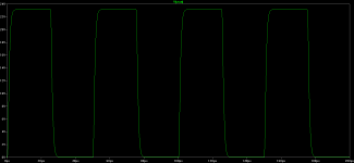
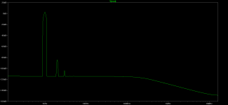
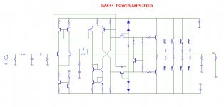
The amplifier in #20 has many hours of testing for all kinds of stuff. The ones in #28 and #32 should also be fine. Please find attached curves for #28.
Attachments
hope i get it.just removed one resistor.
It should work. What output devices are you planning to use ? Changes you make from the original may alter user experience.
TO3
If im going to use to3 casing i would mount it directly on the main heatsink without the use of L bracket.and mount also the board on the same heatsink.if you have a book of randy sloan theres a picture of his basic ef design rated 6o watts.i will post saturday of completed randy sloan basic ef amp.but this one i made it.and i dont want to miss something on this amp.
It should work. What output devices are you planning to use ? Changes you make from the original may alter user experience.
If im going to use to3 casing i would mount it directly on the main heatsink without the use of L bracket.and mount also the board on the same heatsink.if you have a book of randy sloan theres a picture of his basic ef design rated 6o watts.i will post saturday of completed randy sloan basic ef amp.but this one i made it.and i dont want to miss something on this amp.
Last edited:
Hi Joel,If im going to use to3 casing i would mount it directly on the main heatsink without the use of L bracket.and mount also the board on the same heatsink.if you have a book of randy sloan theres a picture of his basic ef design rated 6o watts.i will post saturday of completed randy sloan basic ef amp.but this one i made it.and i dont want to miss something on this amp.
Try to get your hands on one of those heat sinks that have an L extension which is part of the heat sink such as used on Krell KSA-100 Mk II. Wish you the best on this project, I do hope you like it. Do keep this thread up to date with your progress.
kind regards
Is this a Class A amp ???
Hi Homemodder. Not A. The planet is going green. What will happen when they pass regulation to ban class A ?
- Home
- Amplifiers
- Solid State
- SYMEF amplifier