@The Shaman: if you are reading mate, did you end up getting any result with the DPS600? i'm probably looking more at the dps500 or 600 for woofers and the 400 for the other amps be they mid-woofers or tweeters depending on where the LPUHP ends up
Still waiting on AudioPower to ship the supplies.

The first part of the order (6 supplies) is supposed to be boxed up and ready (they even sent me pics) but have been waiting on UPS to collect for over a week now.
I've been told the second part of the order (another 10 supplies) were boxed up last night.
Time will tell.
Hi all,
I apologize for the problem, the main delay (I refer to the version / DA of the DPS-600) is linked to the external manufactory for the power-unit , right in this new version (now in stock). there are no problems for the standard version of the DPS-600 (the same as that sent to Owen, but with regulators, including, for drivers vcc) and remote control 2Pin
It is not easy to hear Owen, this can be a problem that extends the time.
Regards
Hi Owen,
This works for me
Best Regards,
Steve
Works for me too.
Hi Guys,
Now that people have everything they need to start building, I have a few goodies to post up regarding bias settings and the SMPS I've measured.
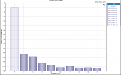
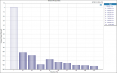
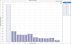
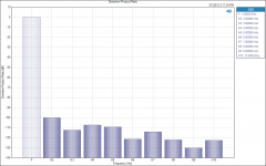
I'll start with bias. I took a whole pile of distortion and distortion product ratio (DPR) measurements at various different bias levels. This way, each individual user can make their own decisions about what levels to bias at.
Here's the test setup:
Amp setup = SE
PSU = DPS400 with PBTU
+/- 52VDC on Mosfets
+/- 64V on LME
Bias levels from 25mA to 1A.
Gain = 28dB
Input = 225mV RMS
Output = 3.9W
Load = 8 ohms
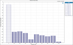
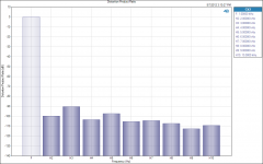
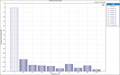
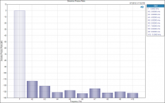
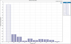
The first set of attached images show the distortion product ratio at different bias currents.
Overall bias levels are (in order):
25mA
50mA
100mA
150mA
200mA
250mA
300mA
350mA
400mA
500mA
600mA
700mA
800mA
900mA
1000mA
Now that people have everything they need to start building, I have a few goodies to post up regarding bias settings and the SMPS I've measured.
I'll start with bias. I took a whole pile of distortion and distortion product ratio (DPR) measurements at various different bias levels. This way, each individual user can make their own decisions about what levels to bias at.
Here's the test setup:
Amp setup = SE
PSU = DPS400 with PBTU
+/- 52VDC on Mosfets
+/- 64V on LME
Bias levels from 25mA to 1A.
Gain = 28dB
Input = 225mV RMS
Output = 3.9W
Load = 8 ohms
The first set of attached images show the distortion product ratio at different bias currents.
Overall bias levels are (in order):
25mA
50mA
100mA
150mA
200mA
250mA
300mA
350mA
400mA
500mA
600mA
700mA
800mA
900mA
1000mA
Attachments
-
 Distortion Product Ratio 25mA.png48.2 KB · Views: 649
 -
 Distortion Product Ratio 500mA.png47.1 KB · Views: 187
 -
 Distortion Product Ratio 400mA.png46.9 KB · Views: 126
 -
 Distortion Product Ratio 350mA.png46.5 KB · Views: 137
 -
 Distortion Product Ratio 300mA.png46.7 KB · Views: 151
 -
 Distortion Product Ratio 250mA.png46.8 KB · Views: 133
 -
 Distortion Product Ratio 200mA.png46.7 KB · Views: 609
 -
 Distortion Product Ratio 150mA.png47.1 KB · Views: 621
 -
 Distortion Product Ratio 100mA.png47.4 KB · Views: 632
 -
 Distortion Product Ratio 50mA.png47.8 KB · Views: 631
Last edited:
And here are the rest:
Attachments
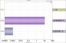
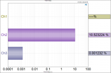
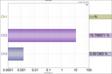
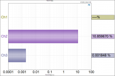
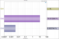
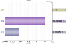
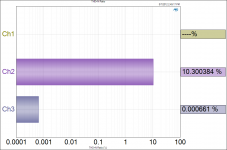
Next up I've got the actual THD+N expressed as a percentage for each bias level.
Same order as last time, but the 900mA measurement is omitted. The only relevant channel is CH3. The other two are disconnected.
Keep in mind that these are THD+N measurements, and as a result they stay about the same at higher bias levels even though the distortion continues to drop if you look at the DPR graphs. This is a sign that the noise levels are becoming dominant at higher bias levels as the distortion starts to drop below the noise floor of the amp with this supply.
Attachments
-
 THD+N 225mV 8R - 500mA.png61.8 KB · Views: 134
 -
 THD+N 225mV 8R - 400mA.png63.5 KB · Views: 125
 -
 THD+N 225mV 8R - 350mA.png62.9 KB · Views: 121
 -
 THD+N 225mV 8R - 300mA.png64.4 KB · Views: 124
 -
 THD+N 225mV 8R - 250mA.png64.7 KB · Views: 104
 -
 THD+N 225mV 8R - 200mA.png64.3 KB · Views: 102
 -
 THD+N 225mV 8R - 150mA.png64.8 KB · Views: 106
 -
 THD+N 225mV 8R - 100mA.png64.8 KB · Views: 106
 -
 THD+N 225mV 8R - 50mA.png65.5 KB · Views: 136
 -
 THD+N 225mV 8R - 25mA.png65.2 KB · Views: 163


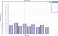
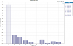
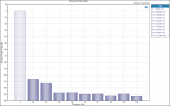
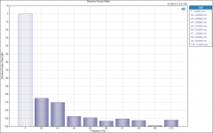
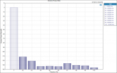
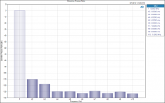
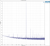
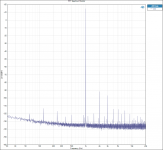
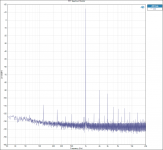
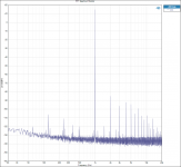
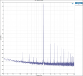
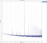
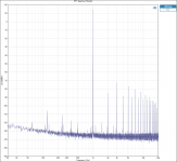
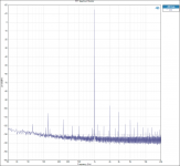
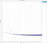
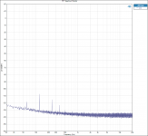
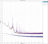
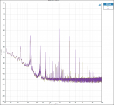
Lastly I've got the FFT's for each bias level. These essentially show what the DPR graphs are showing, except you also get to see the effect of the 120Hz noise from the PSU and the noise floor itself.
Notice how the 120Hz noise is lowest at midrange bias levels, and climbs at both low and high bias levels.
It's also worth noting that the supply will not start at higher bias levels, but seems to be okay with them when it's adjusted after startup. higher bias levels might require active cooling.
Notice how the 120Hz noise is lowest at midrange bias levels, and climbs at both low and high bias levels.
It's also worth noting that the supply will not start at higher bias levels, but seems to be okay with them when it's adjusted after startup. higher bias levels might require active cooling.
Attachments
-
 FFT Spectrum Monitor - 225mV 8R - 500mA.png105.3 KB · Views: 81
 -
 FFT Spectrum Monitor - 225mV 8R - 400mA.png103.6 KB · Views: 71
 -
 FFT Spectrum Monitor - 225mV 8R - 350mA.png107.8 KB · Views: 76
 -
 FFT Spectrum Monitor - 225mV 8R - 300mA.png106.8 KB · Views: 80
 -
 FFT Spectrum Monitor - 225mV 8R - 250mA.png107 KB · Views: 62
 -
 FFT Spectrum Monitor - 225mV 8R - 200mA.png105.9 KB · Views: 428
 -
 FFT Spectrum Monitor - 225mV 8R - 150mA.png107.4 KB · Views: 426
 -
 FFT Spectrum Monitor - 225mV 8R - 100mA.png106.5 KB · Views: 443
 -
 FFT Spectrum Monitor - 225mV 8R - 50mA.png106.9 KB · Views: 452
 -
 FFT Spectrum Monitor - 225mV 8R - 25mA.png107.9 KB · Views: 466


Overall, pretty much all bias levels above 25mA provide respectable performance, but in the name of balancing the harmonic distortion character of the amp, I'd suggest sticking to levels of 300mA or more.
At 300mA, everything above the third harmonic disappears below the -120dB line, which means all you're going to hear (if anything at all) will be the second and third harmonic.
Additional bias past 300mA basically provides additional gains in distortion reduction, and has a pretty significant effect on the 2nd and 3rd harmonic while pushing the higher harmonics below the -130 dB mark, essentially burying them in the noise floor of the amp. The 600mA bias point seems to be the "point of diminishing returns" where only the second and third harmonic are driven slightly lower at the cost of much more idle dissipation.
If you have a supply that is fully regulated and very quiet, then I would expect a measurable improvement up to and beyond 1A of bias, but make sure you tread into that territory carefully as you might not get any real advantage while suffering the very real disadvantage of much higher utility bills. Everything has its price.
If you're using this as a subwoofer amplifier, I would seriously consider a lighter bias level in the name of efficiency. Dropping down to 100mA would be unlikely to have any effect given the higher distortion of most subwoofer transducers. In the midrange and higher frequencies I would suggest sticking to 300mA or 400mA for a good balance between idle power consumption and performance, while really critical applications could push for 600mA to obtain the highest level of performance. This might make perfect sense in a lower power amplifier with lower voltage rails. If you like class A, then go right ahead and push up to or beyond the 1A mark. Just please make sure you have a very good power supply and sufficient heatsinking as things will get very hot very quickly, and only the best of sources and loads will be able to make use of the minute performance gains these bias levels provide.
Enjoy!
Owen
Hi Owen, I want to commend the work of development of your amplifier, thank you also,for taking the time to measure.
Now the segment 20-800Hz is very similar to the measure that I have done in the laboratory. my comment just on this segment is very positive, being critical for a SMPS in general.
then remains the problem when unplug the cord from the 230VAC? or have you solved? and, remote control is ok?
Regards
Now the segment 20-800Hz is very similar to the measure that I have done in the laboratory. my comment just on this segment is very positive, being critical for a SMPS in general.
then remains the problem when unplug the cord from the 230VAC? or have you solved? and, remote control is ok?
Regards
Now for the supply specific measurements. I measured the amp output noise floor, the output of the supply itself, the output ripple and all the operating conditions. Here are the test conditions for the DPS-400 and PBTU:
Mains AC voltage 233VAC
Primary Output Voltage @ 400mA: +/- 51.6VDC
Low Current Output Voltage: +/-62.5VDC (should be adjustable)
Maximum unclipped power @ 8 ohms: 122W 0.001% THD+N
Maximum output power @ 8 ohms and 1% THD+N = 128W
Maximum output power @ 8 ohms and 10% = 155W
Issues with the setup:
1. Both DPS-400 supplies that I have received will not start up with the amp set to anything over 250mA bias. I believe AP2 can resolve this, but I cannot provide more testing on this front.
2. If the power switch is used to bring the supply up and down, the behaviour is very good. There are no audible clicks and pops on the output, and voltage ramps up and down predictably and smoothly. If the plug is pulled, however, there are large transients caused by the supply dipping below its under voltage limit and shutting down, then immediately starting back up again. This happens as many as 10 times before the supply fully turns off, and the transients on the output are large. I would say that this behaviour is unacceptable unless a relay is used. AP2 will need to verify if this can be fixed. Overall, it means that you won't have a problem if you connect the supply and use the intended power switch on the supply, but if your power even goes out while the amp is on, you will get some mean transients on the output. Probably fine for a subwoofer, but certainly not for a fragile midrange or fullrange and absolutely not for a tweeter.
3. The PBTU is a very slick capacitor board with a full set of regulators for the HV output, but the adjustment pots for the regulators do nothing at all. It might just be the target level that needs to be adjusted, but this needs to be fixed so that the regulators are actually regulating.
4. The 120Hz noise (and subsequent harmonics) are a little higher than I would have liked
5. I cannot speak to the long term reliability or safety of the supplies. I had no issues throughout my testing, but I have done absolutely no work in terms of testing the safety features or suitability of these supplies. This is a serious liability area, and I just can't go there. Each user needs to make these decisions for themselves.
Things that were good about the setup:
1. It's very small
2. It's very light
3. It's pretty low cost, especially if you want monoblocks.
4. Output noise performance is very good for an SMPS. It nearly rivals a regulated supply.
5. Rail stability under load is quite good.
6. The power on/off and indicator LED work like a treat.
7. It's ready made, and other than cables, it's plug'n'play.
8. It sounds good.
Regards,
Owen
Attachments
-
 DPS400 - 400mA GND INPUT - 80k.png110.5 KB · Views: 98
 -
 DPS400 - 400mA GND INPUT.png97.9 KB · Views: 89
 -
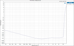 THD+N Ratio vs Output - 8R - DPS400.png83.2 KB · Views: 145
 -
 FFT Spectrum Monitor - supply 400mA.png139.4 KB · Views: 89
 -
 FFT Spectrum Monitor - supply 400mA 10W 1K.png133.4 KB · Views: 82
 -
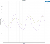 Scope (Signal) 2.png70.2 KB · Views: 84
 -
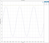 Scope (Signal).png69.7 KB · Views: 84
excellent mate!! thanks so much for taking the time Owen, so looks like the sweet spot is about 600ma after which there is little/no improvement. is that about right?
ah sorry mate, I hadnt seen your above posts that confirm this before posting. excellent. so what was the highest level the supply would start up into?
edit 2: haha you answered that too. hmm the transients are a big concern for me given i'm running this in a digital crossover. maybe enough to rule it out for me. so you didnt get to do any testing of the higher level regulated supplies from AP? i'll probably be sequencing the start/stop with an MCU, but that still doesnt cover me for a problem at the wall and I cant live with that. do all the supplies have this
looks as if running bias even higher than 600ma might be doable for me, given the max I would expect to put out at this stage would be 75wpc into the midwoofers, maybe higher soon when I get the woofers added, but for now even that is overkill, probably more like 40-50w and i've got decent heatsinks
what is the PBTU? link? found it, google was friendly. ok seems a bit low capacitence for this no? is it available with the caps unpopulated AP2?
maybe given my needs i might be better to stick with linear regulated DIY.
Last edited:
I still want to thank Owen for the time spent on the measures.
Just for clarity, this problem of "restart", when the ac cable is disconnected, occurs due to a modified connection with resistors. (Modification required to solve the startup with a high bias), then, is not a defect of this SMPS . I can certainly solve the startup with a high bias in another way (of course reset resistors in the original position).
When possible, show pictures of the DPS-400 in startup with 400mA without the defect.
@ Qusp:
yes, you can have the PBTU-2 kit (pcb+heatsink + all comp. without capacitors)
for this, I need to know the total amount.
I have little time to devote to this DPS-400, maybe I should be encouraged ...
in my opinion, to see how far the DPS-400 to other similar SMPS, you should compare the measurements.
@ Owen: you can show a photo of DPS-400 + PBTU you have on the table? (complete with connections to the amplifier)
-------------
If it can be useful to understand the reliability, the DPS-400 has been in production since 2005 with a small release (no defects)
Regards
Last edited:
This abominable behaviour completely rules out this PSU for any situation where mains power could be interrupted before it reaches the household distribution board.2. If the power switch is used to bring the supply up and down, the behaviour is very good. There are no audible clicks and pops on the output, and voltage ramps up and down predictably and smoothly. If the plug is pulled, however, there are large transients caused by the supply dipping below its under voltage limit and shutting down, then immediately starting back up again. This happens as many as 10 times before the supply fully turns off, and the transients on the output are large. I would say that this behaviour is unacceptable unless a relay is used. AP2 will need to verify if this can be fixed. Overall, it means that you won't have a problem if you connect the supply and use the intended power switch on the supply, but if your power even goes out while the amp is on, you will get some mean transients on the output. Probably fine for a subwoofer, but certainly not for a fragile midrange or fullrange and absolutely not for a tweeter.
For any SMPS PSU to behave like this is plain and simple "BAD DESIGN"
I'd suggest sticking to levels of 300mA or more.
This issue must be resolved.......................
Issues with the setup:
1. Both DPS-400 supplies that I have received will not start up with the amp set to anything over 250mA bias. I believe AP2 can resolve this, but I cannot provide more testing on this front.
How can the amplifier designer recommend >=300mA bias current and then tell us that the PSU won't start up at the recommend bias setting.
Have the design team gone bonkers? or is it blinkered?
Why the f... are we considering an SMPS that basically does not work with the amplifier?
- Home
- Amplifiers
- Solid State
- "The Wire AMP" Class A/AB Power Amplifier based on the LME49830 with Lateral Mosfets