Hi, I recently bought a 405 amp with 34 pre-amp. One channel of the amp was faulty (both fuses blow at turn on). With the 405 came two Ebay clone boards. They are similar to the ones I've seen on Ebay except that they have a heatsink fitted and the output transistors are of the can type. Anyway... I decided to keep the 405 as quad intended and sent the amp module off for repair, meanwhile whilst I'm waiting the clone boards kept crying out to be tried.. so one +/-50v supply later (and with only one amp connected, just to be on the safe side) I turn on. All seemd fine until I connected an input. Then much distortion and hum and then came the smoke (not a lot and I can't see the damage). I have since tried the other channel and all is well. The first channel however remains loud and distorted but not smoking. I'm certain that all wiring etc was ok, the only two things I can think that I might have done wrong are; 1, overloading the input on the first attempt and 2, not running a separate 0v to the heatsink. Any ideas what I've done to my project??
Hi.
I have a lot of experience with 405......clones...originals....
Can you post some pictures..? There can a lot of things go wrong. I suspect that you somehow miss the ground conection. Original board have a bolt which connect ground to the heatsink.....If there was no ground on the board it oscillates.....and probably burn the 10E resistor at the output zobel network...
Because I'm in the London theese days maybe we can meet and I can help you....also with repairing originals....
Regards, Taj
I, too have had a smoked tweeter as a result of the faithful cloning of the original grounding error on the Quad circuit diagram. As I recall, the input ground is connected to the power ground by a low value resistor, but when fitted in the Quad enclosure, all grounds were connected together. On the diagram, the speaker ground return is shown going back to the input ground, not the power ground, so if you don't connect the input ground to anything, the circuit oscillates and bang goes your tweeter!
Hi.
I have a lot of experience with 405......clones...originals....
Can you post some pictures..? There can a lot of things go wrong. I suspect that you somehow miss the ground conection. Original board have a bolt which connect ground to the heatsink.....If there was no ground on the board it oscillates.....and probably burn the 10E resistor at the output zobel network...
Because I'm in the London theese days maybe we can meet and I can help you....also with repairing originals....
Regards, Taj
Brilliant!! Many many thanks! R10 had indeed gone down to 1K. Smiles abound once more!!
Hi, many thanks for the help so far... Replacing R10 with 1k8 as shown on the board got the channel working but you're right, both r39s have got hot, they still measure 10E though!
I have realised however that each channel works if supplied from a different source, the minute I try the same source, hum & distortion on both channels. The same happens if I link the two input signal earths or try to put the signal earth to the chassis.
Is this because of burnt R10s or does r10 get hot because of the lack of earth?
I seem to be going round in circles, not certain of cause or symptom!
If you get a humm when you join channels, that is a ground loop.
If the 10R resistor which appears to be part of the Zobel network is getting hot, the amplifier is oscillating.
Signal earth should not be on the chassis. Connect that to safety earth. The input sockets should be isolated from the chassis. Connect both signal grounds at one point only, and then connect this point to 0V star earth at the main supply capacitors, via a 10 ohm resistor. Somewhat like this:
An externally hosted image should be here but it was not working when we last tested it.
Hi sorry for late reply...I have a lot of job, I'm trying to rent a flat in London....
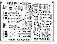
Well quad. There you have 2 10E resistors at the each board. One is a part of output zobel filter. The other connects both grounds. The power ground and the input ground. And what I think is.....
You have no power ground at your boards so they oscillate and burns zobel resistors....and because amp wants ,,to ground itself ,, it is happening through those 10E resistors (R2) it is even worse if you have unisolated rca plugs bolt to the chasis ......
So you need to connect the power ground to the both boards. It is for an example the opposite side of zobel output network which isn't connected to the output. You have there 10E resistor in series to 100n cap. I don't know which goes to the output and which to the ground but one side is ground and the other is speaker output.
If you need help feel free to ask....and if you need I can send you 405 service manual via email. Mine is
taj.pecnikar@gmail.com
Best regards, Taj
smoking quad clone
read threads on quad 405 clone probems ? i am about to use 405 ljm 2006/v1/2010/v2 . seems to be an issue on gnd of the boards . as both my boards have a connection point marked gnd i am alittle confused . ( nothing new to me ) has anyone not had a problem ? and how do they perform once finished . i have only recently started down diy rd after 40 yrs all tube then . also i want to mount tip42s on single heatsinks ? i thank all who can help bernard
read threads on quad 405 clone probems ? i am about to use 405 ljm 2006/v1/2010/v2 . seems to be an issue on gnd of the boards . as both my boards have a connection point marked gnd i am alittle confused . ( nothing new to me ) has anyone not had a problem ? and how do they perform once finished . i have only recently started down diy rd after 40 yrs all tube then . also i want to mount tip42s on single heatsinks ? i thank all who can help bernard
About 405....
Original quad 405 have ground connection on each board. It is connected to the heat sink directly via bolt.....This is power ground which goes to speakers and to the 0V on power capacitors......
The other ,,ground,, goes only to the inpput connector which is isolated from enclosure.....This is signal ground.
Both grounds are connected with 10E resistors. On each board.....
So those ebay boards seems ok to me....if I find right item.....
About drivers. Drivers are mounted on the same heatsink with output transistors at the original amp which ensure termal coupling......and there is one more thing. One of those ,,drivers ,, is in fact output transistor of the small class A amplifier which is boosted with class C ,,dumpers,, and it dissipates a lot of heat. So it would not be good idea to place it on some small heat sink.....
And of course you can earn some oscillations as well....
So my advice is : DO NOT
Best regards, Taj
http://www.ebay.co.uk/itm/2pcs-QUAD...640804124&po=&ps=63&clkid=2729918165847663265

The eBay kit is for a 405-1 using an LM301 - its not a good version. They make a big deal about 1% resistors etc. where the whole point of the design is that it doesn't care (mostly) about component tolerances.
They even point out how accurate the 3uH L2 inductor is - in actuality, it should be 2.82uH to balance the bridge.
Odd that they went to all that trouble to make a clone board, then chose an old revision that even Quad themselves heavily updated 20 years ago, let alone everyone else.
All is now well and no need for any more help. I knew it was something stupidly simple. When I finally sat down and got a look at the circuit diagram I realised that the cloners had managed to reverse the lables for the signal in and earth! I hang my head in shame. I'm really sorry to have used up your time, but at the same time really glad to know that there are some really helpful people out there!
At original 405 it was done like that. The centre point of the poer caps goes to the chassis. Speaker returns goes to the centre point. Boards are only bolt to the heat sinks and that's all. No wires no anithing......just bolt. The signal ground goes from board to the input connector....
If you want I can send you a service manual for whole 405 family. Email me...
Regards, Taj
If you want I can send you a service manual for whole 405 family. Email me...
Regards, Taj
I would advice to use the schematic "405-3" by Keith Snook, QUAD 405 Amplifier Information and Modification , http://keith-snook.info/Schematics/QUAD 405 schematic evolution .pdf
Just wish someone could help me make customised circuit boards for it. I have made my own layout accepting alternative sizes of capacitors in order to make more universial.
Just wish someone could help me make customised circuit boards for it. I have made my own layout accepting alternative sizes of capacitors in order to make more universial.
I made some QUAD405 design. But don't know if I have provided version?
have "LJM" letters ON THE BOARD?
Hi, I'm interested in the Quad 405 you sell.
Is the original Zobel issue solved in your design?
I found a LJM 2010 V2 of your design, is this the right one?
RGDS
PEMO
I found a LJM 2010 V2 of your design, is this the right one?
That version has very little in common with later designs.... Snook's 405-3 is the schematic to follow if a modern 405 without issues is the goal. As Snook's version uses fewer components, a new PCB could use components more readily availble. Some PCMs can have alternatives, like 5-10-15 mm instead of just 10 mm.
Roger
Please, can you re-display the image?If you get a humm when you join channels, that is a ground loop.
If the 10R resistor which appears to be part of the Zobel network is getting hot, the amplifier is oscillating.
Signal earth should not be on the chassis. Connect that to safety earth. The input sockets should be isolated from the chassis. Connect both signal grounds at one point only, and then connect this point to 0V star earth at the main supply capacitors, via a 10 ohm resistor. Somewhat like this:
An externally hosted image should be here but it was not working when we last tested it.
I can´t watch the scheme of wiring .
Regards VMA.
oscillating problems
I also bought this quad 405 kit and also have an oscillation problem with same assembled board and did not understand what you mean revers lables for signal in and earth.It seems they are true, not reversed.Please help if you solved the problem.
All is now well and no need for any more help. I knew it was something stupidly simple. When I finally sat down and got a look at the circuit diagram I realised that the cloners had managed to reverse the lables for the signal in and earth! I hang my head in shame. I'm really sorry to have used up your time, but at the same time really glad to know that there are some really helpful people out there!
I also bought this quad 405 kit and also have an oscillation problem with same assembled board and did not understand what you mean revers lables for signal in and earth.It seems they are true, not reversed.Please help if you solved the problem.
- Home
- Amplifiers
- Solid State
- QUAD 405 clone