Each track used 2 to 3 will SA1186 2 SC2837 2.
LAPT power transistors, ultra-high frequency FT, solve the CFP switch distortion.
Tiny hand in the distortion + 0.6 V.
Thanks. I really love that power supply board: it has built in soft start, and speaker protection. No having to try to coordinate 4 different boards. The amp itself is very pleasing. Ers Very clean and all the power you need. I would like to try some speakers that are on the warm side, as it is so clinically clean.
Hello.
After some modifications, I have achieved the making of my L12-2 amplifier and I use it for 3 months now.
First of all, I want to say that I am very pleased of this amplifier :
The sound is very neutral, natural, airy and detailed.
There is no noise, humm or buzz and this enhances the sensation of space and air in the music (my loudspeakers, from the very good french manufacturer "Triangle", are separated by 2.30 meters/75 feets).
The stereo image is very wide and detailed (I have discovered in the mixes some instruments hidden before).
The dynamic is very high and well controlled.
The basses can be very fat or warm, with some attack or some good roundness, so the sound is never boomy.
The highs are clear and not harsh (it depends naturaly of the mix).
To conclude, I strongly recommend this amplifier (with the Sanken transistors). It must be coupled with a very good power supply to give his best.
In fact, I have changed my plans and decided to separate the PSU part from the amplifier to add a regulated stage to the PSU.
I have placed this parts in separate boxes : the PSU in the bottom box and the amplifier box at the upper side.

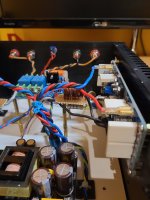
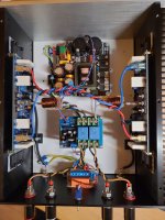
Each PSU (one PSU by channel) is now composed of a toroidal transformer (300VA 2x30v), a rectifier / filter stage (a Wondom product modified with 16 x 4700µF/85v nichicon capacitors for a total of 75 200 µF by channel), a premium regulated stage for +-40V/4.8A average/15A peak (a kit from the Elektor magazine) and a safety loop breaker circuit.
The PSU before and after assembly.


The rectifier / Filter stages (150 000 µF)

The regulated stage (+/- 40v)

The two loop breakers on the same PCB.

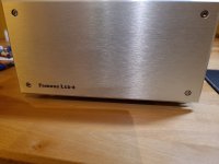
The PSU box ready to be coupled with the amplifier box.

Pictures of the amplifier will come ASAP.
After some modifications, I have achieved the making of my L12-2 amplifier and I use it for 3 months now.
First of all, I want to say that I am very pleased of this amplifier :
The sound is very neutral, natural, airy and detailed.
There is no noise, humm or buzz and this enhances the sensation of space and air in the music (my loudspeakers, from the very good french manufacturer "Triangle", are separated by 2.30 meters/75 feets).
The stereo image is very wide and detailed (I have discovered in the mixes some instruments hidden before).
The dynamic is very high and well controlled.
The basses can be very fat or warm, with some attack or some good roundness, so the sound is never boomy.
The highs are clear and not harsh (it depends naturaly of the mix).
To conclude, I strongly recommend this amplifier (with the Sanken transistors). It must be coupled with a very good power supply to give his best.
In fact, I have changed my plans and decided to separate the PSU part from the amplifier to add a regulated stage to the PSU.
I have placed this parts in separate boxes : the PSU in the bottom box and the amplifier box at the upper side.
Each PSU (one PSU by channel) is now composed of a toroidal transformer (300VA 2x30v), a rectifier / filter stage (a Wondom product modified with 16 x 4700µF/85v nichicon capacitors for a total of 75 200 µF by channel), a premium regulated stage for +-40V/4.8A average/15A peak (a kit from the Elektor magazine) and a safety loop breaker circuit.
The PSU before and after assembly.
The rectifier / Filter stages (150 000 µF)
The regulated stage (+/- 40v)
The two loop breakers on the same PCB.
The PSU box ready to be coupled with the amplifier box.
Pictures of the amplifier will come ASAP.

I have build a LJM L12-2 too. The Amp is powerd by a 300 Watt connex smps +-36 volt. The housing is a little to big, but i tried to use a transformer first.
Awfully i get some hum in the speakers and no chance to get it away. Now, powerd with the smps the hum is gone. The sound is very good as Dasoft wrote. No white noise, death silence.
I have done all changes or mods you can read about at Calvins Audiopage (thanks for the detailed informations). The bias is set to 45mA in each amp. Was not equel before. About+- 5mA differance as i get the boards from Aliexpress. The 2µh coil is not my best work. In other amps i choose 1,3mm copperwire, the coils get exact with on 15mm drill.
Greetings
Peter
Attachments
Hello,
here is the second part of my "making of".
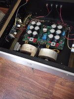
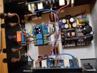
Interior of the amplifier box (with the soft start circuit in the middle back, the shielded transformer of the speakers protection circuit, the speakers protection circuit in the middle and the amplifiers PCB mounted on heatsinks on the sides).

Other view of the components with the AC power filter on the left (in a metallic box).

The speakers protection circuit.

The soft start with thermal protection circuit with the shielded transformer for the speakers protection circuit.

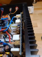
The left channel amplifier PCB with his heatsink before mounting.

The same element installed in the box (with a temperature sensor on the right)

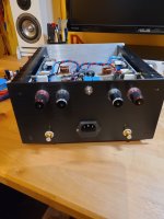
View from the back of the amplifier and the PSU.

View from the front (with amplifier working).

Now I must build the DAC / Preamplifier / volume control...
Thank you every one in this thread for their advice and help.
here is the second part of my "making of".
Interior of the amplifier box (with the soft start circuit in the middle back, the shielded transformer of the speakers protection circuit, the speakers protection circuit in the middle and the amplifiers PCB mounted on heatsinks on the sides).
Other view of the components with the AC power filter on the left (in a metallic box).
The speakers protection circuit.
The soft start with thermal protection circuit with the shielded transformer for the speakers protection circuit.
The left channel amplifier PCB with his heatsink before mounting.
The same element installed in the box (with a temperature sensor on the right)
View from the back of the amplifier and the PSU.
View from the front (with amplifier working).
Now I must build the DAC / Preamplifier / volume control...
Thank you every one in this thread for their advice and help.

I got two boards from this seller too. Powering from +/- 40V and they seems fine to me. How do yours sound?Hello everyone.
I bought 2 boards of this amp on ebay from seller with nickname "toplasers2016", it's ver4 and there is 🐼 in corner and now I would like to know couple questions.
First is there any easy way of testing boards with only multimeter are they legit or I got some fake ones ?
I was measured DC offset on outputs and 1 board is around 12mV and other around 20mV and I was wondering for modification could I just replace R19 with 2k pot without parallel connection with 1.5k resistor and 5k pot and also could I just try to replace some resistors to get on normal DC offset ?
Thanks and please keep in mind I have only multimeter and soldering iron and just a lot of love for electronics and I'm steel noob. 🤓
- Home
- Amplifiers
- Solid State
- L12-2 CFP Output amp 120W*2 8R