
Is this for the secondary side of the transformer? If so, will it get rid of the ripple voltage?
I do have the protection circuit for the chassis and signal ground from Elliott Sound Products recommendations.
I do have the protection circuit for the chassis and signal ground from Elliott Sound Products recommendations.
Attachments
Last edited:
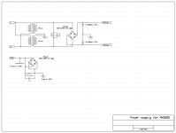
Is this for the secondary side of the transformer? If so, will it get rid of the ripple voltage?
I do have the protection circuit for the chassis and signal ground from Elliott Sound Products recommendations.
It's after power plugin 220v(or 110v. mains voltage?) ac. Before transformer.
Last edited:
Is this for the secondary side of the transformer? If so, will it get rid of the ripple voltage?
I do have the protection circuit for the chassis and signal ground from Elliott Sound Products recommendations.
It's after power plugin 220v(or 110v. mains voltage?) ac. Before transformer. It's dangereus if you don't use proper caps.
Last edited:
Hi guys,
may I suggest you to read this very interesting and accurate post:
LJM L20 V9.0 Amplifier
I think you should increase the bias more to achieve some good result, but be carefull if you have small heat heat sinks.
Good luck!
may I suggest you to read this very interesting and accurate post:
LJM L20 V9.0 Amplifier
I think you should increase the bias more to achieve some good result, but be carefull if you have small heat heat sinks.
Good luck!
Last edited:
LJM L20 V9.0 Amplifier
I think you should increase the bias more to achieve some good result, but be carefull if you have small heat heat sinks.
Why do you think so?
CFP is very unique. EF outputs have consistent behaviour regarding bias, i.e. the more bias the better or at least have diminishing return. CFP otoh is different. There is optimum bias where going lower or higher will reduce the performance. But the position of this optimum bias is really dependent on the design and parts used.
I have read people mentioned that CFP is suitable for class-A only. May be his experience is with class-A CFP. Because a class-A CFP will be optimum at class-A and the performance will suffer with bias change to class-B. Vise versa for class-B CFP.
LJM seems like to prevent posting the real schematic. But if the schematic found in this thread is accurate, the bias should be lower than most EF output. But he is using 60MHz output and the design seems optimized, I would guess the optimum bias is higher than average CFP.
I'm not sure but I think I have observed something during biasing one of my similar CFP amp.... Let's say the optimum bias is 10. When I set the bias to below 10 at no signal, soon with the signal it will go to above 10... When I set the bias to above 10 with no signal, soon with the signal the bias will go to below 10... It is rock stable with little to no variation at the optimum bias...
I'm not sure if this behavior can be observed in other CFP designs though.
..I think you should increase the bias more to achieve some good result..
Dear John (*),Why do you think so?
...

My decision to increase bias was based purely on measurements. Increased bias has substantially reduced crossover distortion and eliminated high frequency oscillation. In case of L12-2 I went above 15 mV potential drop simply because I could and it paid-of. I use large heat sink and adjust bias in accordance to measurements. On larger heat sink I was able to adjust bias without significantly increasing temperature. Heat sink is now warm, nothing more that deserves some serious measurements.
In my humble opinion, the problem with low bias is not of technical nature, rather economical. The problem is to make a good amplifier at competitive price. Once you increase the bias, dissipation increases accordingly. More importantly, the weight of the heat sink increases and transportation costs from China go too high. The result is a poor-mans blameless amplifier. Fortunately, this shortcoming can be easily corrected and the LJM amplifiers have great sound and great potential to become real blameless amplifiers, but this requires investment into larger heat sinks and increased bias.
(*) Do you remember that TV series with Judd Hirsh?
Last edited:
Dear John (*),
(*) Do you remember that TV series with Judd Hirsh?
No, but I know
My decision to increase bias was based purely on measurements. Increased bias has substantially reduced crossover distortion and eliminated high frequency oscillation.
Of course measurement doesn't lie but don't know why I got the feeling that you confused CFP with EF. This is not about efficiency.
Increasing bias will increase crossover distortion. It is a different kind of crossover distortion.
I think it is a good decision to provide a fixed bias (no VR) for CFP amplifier kits. As long as the transistors are as specified there is no need to change the bias.
Of course, high bias have merits too. But in case of CFP that is optimum at low bias, the price to pay is high. If I want high bias or even class-A I will change the design, not just increase the bias.
I don't know why the complexity in the LTP (may be just to confuse people
). But I found that the solution to this bias issue and the stability issue with CFP lies almost exclusively in the local feedback arrangement of the Sziklai pair.Thanks John,
The first measurements were really dissappointment, not just for L12-2 but also MX50SE and L20.5 had awful square wave response. Rising and falling edges were broken lines, the rest indicated there was oscillation. Experimenting with bias yielded significant improovement. I was astonished that I had to go beyond the suggested 15 mV, but that's the reality, despite the lack of compliance with theory. I'm not sure what's the reason or is there some theoretical explanation. I am just a chemist after all, a humble newbie in this area. But what I know is that the rel world imperfections are awkward features that work against simplistic theoretical explanation. So, for practical reasons I have decided to leave bias above the theorethically acceptable value.
But it sounds good now and measurements are better.
The first measurements were really dissappointment, not just for L12-2 but also MX50SE and L20.5 had awful square wave response. Rising and falling edges were broken lines, the rest indicated there was oscillation.
Oh I see. Measurements don't lie. But are you sure you were measuring LJM's products (with specified transistors)?
But honestly I'm confused too to see the phase compensation circuit in the LTP. Amp with this topology should be rock stable with only 68pF Miller cap on the VAS. Unless that is a trickery or it has better performance than the usual Miller compensation. Coz I too know a better solution than the usual compensation technique.I would appreciate very much solution that would improove these amplifiers without the need for changing the bias....Coz I too know a better solution than the usual compensation technique.
I have verified, boards aren't fake. Original LJM. I also measure all components before soldering, without exceptions. I have also paired all transistors as I had at disposal more than 50 each.
I would appreciate very much solution that would improove these amplifiers without the need for changing the bias.
Which schematics, exactly?
Regarding compensation, there are many techniques. The secret is not which one but why (it's not just for Nyquist stability). But my technique might be inaudible especially in an audio chain full of errors.
But in most amplifier schematics there are usually many things that can be improved. Sometimes I'm confused why it is out of people's attention. Most probably because they cannot hear it. But during its progress I can see that later amps from known designers are getting better and better. Probably due to user reports regarding sound improvement.
With the schematics on post #14, I can see that this is already tuned. I will probably disagree with the LTP. It seems there is an effort to improve the low PSRR of the CFP but in my experience the sound is never better. This is only visual check. Simulation will reveal more.
Dear John,
I was clear, we are talking about the LJM L12-2. Correct schematics is published here and also on the Calvins website. At present the main subject of conversation was reduction of distortion. You have stated that you know some alternative method.
It would be really kind of you to share your method with us, your colleagues, friends. But please, clearly and speciffically tell us how can we attain improvement. What should be changed and how.
I do indeed appreciate your contribution.
I was clear, we are talking about the LJM L12-2. Correct schematics is published here and also on the Calvins website. At present the main subject of conversation was reduction of distortion. You have stated that you know some alternative method.
Is it the one in post #14? Is this amp good? If distortion is the goal, my target will be increasing the driver's collector resistor. But 150 is already spot on. By increasing this the stability issues will come. One solution is adding feedback resistor at the emitter end. This will reduce the current on the driver and may lead to the use of small signal transistor for the driver, which has benefit to bandwidth and stability and probably distortion too. But CFP distortion is very low already. If LF distortion is the goal, may be this simple topology is not suitable.
My alternative method was with the compensation. There are many methods and nobody talk about which one is better. So there is no reason that mine is better. I think what people see besides stability is slew rate nothing else.
BTW, in my experience, the most improvement to any amplifier schematics is by choosing the better/right transistors. Here I will use the fastest transistors available (of course not the 1G ones). This only require knowledge about stability.
BIAS Question to be clear
I have the LJM L12-2 VER4. I've read that the quiescent current has been set by LJM to be 40ma. I'm guessing this is per board? My board has the 0.1 ohm collector resistors. So doing the math... .004 (4mv) divided by 0.1 (Resistor) = .040 (40ma). I'm assuming this is across one side of a .1 ohm resistor. So I would measure and adjust to 4mv or 8mv across both resistors. If this is true, total current per board would be 80ma.
If it's 40ma per board, I would adjust for 4mv across both resistors or just 2mv across one of them.
Please let me know if this is correct.
First, thank you very much for your contribution to this conversation. You have been very helpful to me.I have the LJM L12-2 VER4. I've read that the quiescent current has been set by LJM to be 40ma. I'm guessing this is per board? My board has the 0.1 ohm collector resistors. So doing the math... .004 (4mv) divided by 0.1 (Resistor) = .040 (40ma). I'm assuming this is across one side of a .1 ohm resistor. So I would measure and adjust to 4mv or 8mv across both resistors. If this is true, total current per board would be 80ma.
If it's 40ma per board, I would adjust for 4mv across both resistors or just 2mv across one of them.
Please let me know if this is correct.
To avoid any confusion whatsoever first visit Calvins web site and go directly to "L12-2 modifications". Click to image of the amplifier. In the left upper corner you may read "bias:" and below the values: "7.7 mV to 8.8 mV over R13 and R21". That is correct.
However, before you turn on you can measure resistance between the "OUT" connector and the middle pin of any power transistor. You can use this value to calculate the actual current from the measured resistance and potential drop.
On my board I have adjusted potential drop to slightly above 15 mV because I have observed crossover artefacts at values lower than 15. Needless to say, actual parameters of your board may differ but Calvins' suggested values "7.7 mV to 8.8 mV over R13 and R21" are fine.
Decision is entirely yours.
Calvins' suggested values "7.7 mV to 8.8 mV over R13 and R21" are fine.
Assuming that Calvin is correct, Always pick the highest, i.e. 8.8mV...
R=0.1, V=8.8mV, I=88mA.
R=0.22, I=88mA, V=19.36mV.
This is because when you listen by ears, the more current will give gradual increase in quality (this is correlated with lower crossover distortion) until small increase in current will turn the sound quality into worse. So the best one is the highest current very close to the bad one.
So this is the part about Calvins mod suggestions...
Procedure:
Shortcut the input connector.
-
Jumper from „In“ to „gnd“
Testpoints R13:
-TP1 to TP out 7.7mV – 8.8mV
or Testpoints R20:
-TP2 to TP out 7.7mV – 8.8mV
It say OR...So over both R13 AND R20 you would get 15.4 to 17.6 mv...
Procedure:
Shortcut the input connector.
-
Jumper from „In“ to „gnd“
Testpoints R13:
-TP1 to TP out 7.7mV – 8.8mV
or Testpoints R20:
-TP2 to TP out 7.7mV – 8.8mV
It say OR...So over both R13 AND R20 you would get 15.4 to 17.6 mv...
- Home
- Amplifiers
- Solid State
- L12-2 CFP Output amp 120W*2 8R