stop being a tease and give us the links to your posts...... with just one part change and not adding anything to the blameless the performance of the blameless can be improved, this was well known since 1987....................... Also regarding the vas it is possible to lower THD if that is your perogative by upto 30 % at low and 25 % at high frequencies better than blameless if you follow more modern technology (1994) and without reverting to TMC or TPC while using only one more device
Also regarding the vas it is possible to lower THD if that is your perogative by upto 30 % at low and 25 % at high frequencies better than blameless if you follow more modern technology (1994) and without reverting to TMC or TPC while using only one more device, (you wont get there if you thinking of conventional cascode or hawksford cascode).
30% lower distorsion is a very marginal improvement , mind you...
")
Is it really??... try to do better with the current ideas presented in this forum. I am being on the cautious side, replacing Ostrippers vas design for DIYAUDIO with mine I easily half his 1khz THD figure and 30 percent on his 20Khz figure. This translate to his amps 1Khz figure going down from .00060 to .00026 and 20khz figure from .001 to .000824, not so insignificant dont you think, even Self would be proud. Dont forget the law of diminishing returns.
Member
Joined 2009
Paid Member
Bigun, Im not sure what THD figures youre aiming at...
I'm not aiming at a THD figure per se. I believe I will be satisfied with a THD of around 0.01% if high order harmonics are kept low.
The way I see it, the global OLG needs to be sufficient to provide some damping factor and tame the x-over artifacts. The input stage is less of a worry than the output stage. On paper it appears that the higher the fb factor the lower overall distortion but there also appears to be a lot of opinion from those who have done much more than I, that too much fb can have undersirable consequences on the sound. This gets into the 'subjective' and that's a can of worms but I'm willing to learn from others and so I'm aiming for around 20dB - 30dB of global nfb. I note that higher fb factors drives the need for even greater care with layout and compensation. I believe adequate nfb is already available with the design I've posted.
I will be using local feedback (i.e. LTP degeneration) and nested feedback (i.e. from the VAS) to control the fb factor around the output stage.
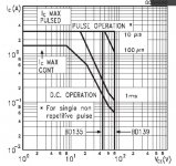
I'm still looking for opinions on how hard to push the Vceo for a BD140 ?
Last edited:
Member
Joined 2009
Paid Member
it's rated at 80Vce0.
I cannot recall seeing data for SOA de-rating for the higher voltages (>=20Vce) nor for the shorter transients (<=100ms).
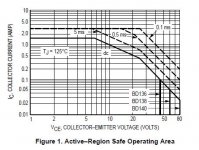
The datasheets for both the BD139 (first graph) and BD140 (2nd graph) don't indicate any de-rating required for Vceo at the current levels I'm contemplating using it at. What I don't have any experience of is whether I'm courting trouble stressing it during clipping at max Vceo, or whether the manufacturers tend to be conservative with their ratings in this regard. For normal listening levels the device will see much less than the max rating and I don't plan to use it as a guitar amp with lots of clipping going on.
What about using a 2SA1837 - I have some on hand. They have plenty of Vceo, but more capacitance than a BD140 (and Ft is lower too, more like < 70MHz at the currents I'll be using). Do I have to worry about capacitance and lower Ft if I'm using it as an EF though ????
Attachments
Last edited:
What about using a 2SA1837 - I have some on hand. They have plenty of Vceo, but more capacitance than a BD140 (and Ft is lower too, more like < 70MHz at the currents I'll be using). Do I have to worry about capacitance and lower Ft if I'm using it as an EF though ????
The 2SA1837 will be no better than a BD140 unless it is for use as driver..
Best would be to use 2SA1145/2SA1360 or equivalent device if it s for VAS purposes.
Last edited:
Member
Joined 2009
Paid Member
Ah yes, the 2SA1360 - a very nice option. I may consider that for the final HT amp build, but I've decided for this prototype to stick with the BD140.
I'll add a few more items to the amp, a zobel on the output for both stability margin and also as a block for any injection of r.f. into feedback loop from the speaker wires. A pot for dc-offset and a pot for dc-bias of course. And with Hugh's blessing I'm going to use the feedback topology from AKSA itself.
I think that's it ? - So, now it's a case of building it and tweaking it.
I think I'll restrict myself to what I can lay my hands on for this build - my wife is rather keen on seeing my junk pile in the basement whittled down. Fortunately, I don't think I'll have to compromise the sound quality at all but it means I'd better collect the parts together to see what sizes they are and then think about a board for it.
stop being a tease and give us the links to your posts.
Sorry Andrew
Its my IP and untill someone stumbles accross the technique I wont be showing it.
As far as improving the blameless vas with no add-ons simply change the vas EF to a mosfet. Im pretty sure youll understand why this would improve THD. It works mostly on the lower frequencies, below 5 khz, 20khz THD can remain unchanged if you use a very good mosfet, the problem being ciss. Samuel Groner has shown this technique on his paper he showed here on Diyaudio. It was patented in 1987 by Van Alstine and long used by me and others, not here on diyaudio though. Theres even one commercial violation of the patent but I dont think it was intentional or brought about any legal consequences.
What about using a 2SA1837 - I have some on hand. They have plenty of Vceo, but more capacitance than a BD140 (and Ft is lower too, more like < 70MHz at the currents I'll be using). Do I have to worry about capacitance and lower Ft if I'm using it as an EF though ????
Bigun you can use this as a guide, higher vceo, higher early voltage and lower THD but only at lower frequencies (below 1KHZ). It about only effects 2nd order harmonics. Higher cob causes higher THD at high frequencies.
So using the toshibas will get you lower 2nd harmonics and lower HD below about 1khz but higher 20khz HD. The bd140 will have the opposite effect. Also the lower early voltage device will nearly in all cases have a more hiraga like distortion distribution although at higher overall THD levels than the high early voltage device. From this you can reason why the optimum for lowest vas THD is a high vceo and low Cob part.
Beware of some toshiba datasheets, they are somewhat optimistic especially the 2sa1837 pair, 2sa1930 and the 2sa1360 pair, they are not as good as the datasheet makes them to be, put them on a curvetracer and be surprised.
BTW if you give me a email address I can mail you the NAD schematics.
Member
Joined 2009
Paid Member
higher vceo, higher early voltage and lower THD but only at lower frequencies (below 1KHZ). It about only effects 2nd order harmonics. Higher cob causes higher THD at high frequencies.
...
Beware of some toshiba datasheets, they are somewhat optimistic
That's good information, thanks !
Last night I discovered that my junk box includes parts from an old Onkyo amplifier. Not just the Sanken power devices I showed earlier, but the small signal parts (matched JFETs) and drivers. Amongst them is what looks like a suitable VAS device (Cob 3.5pF) but the packaging is not ideal for running it warm.
you have a PM.BTW if you give me a email address I can mail you the NAD schematics.
Member
Joined 2009
Paid Member
Any good reason I shouldn't build the circuit upside down, npn for LTP ???
Npn LTP is good as well....
Member
Joined 2009
Paid Member
Npn LTP is good as well....
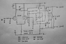
My thought with the upside down circuit was to allow future experiments with a triode LTP (see attached). The trouble is, it's getting bit tight for space in the chasis for tubes and heater supplies.
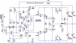
The 2nd attachments shows the more-or-less final schematic in a conventional arrangement. Compared with what's indicated here, I will use lower Cob devices for the VAS since this is a known opportunity for improved sound, and also a higher hfe device for the Vbe multiplier, for a marginal improvement in bias accuracy.
I'm considering using two output pairs for better linearity into more difficult loads and some small adjustments to the output topology may be explored before finalizing.
Should I be worried about noise in the high valued feedback resistor from the VAS ? I've shown a fairly high value of 5.6M but this will likely be reduced to the range 1M to 2M if listening tests confirm a benefit.
Note the additional resistor, R2, in the feedback network. Hugh tells me that it has beneficial effects on the sound (I believe this topology was blabbed in the 'baby aksa' thread) so I will include it here. A side benefit according to Rod Elliot maybe improved transient recovery [Power Amplifier Clipping ] . I may implement a larger feedback cap.
Attachments
Member
Joined 2009
Paid Member
I haven't forgotten about this project yet
I want to re-use my TGM1 amplifiers as they are built and populated so I'm looking to see what approach for TGM4 will be easiest to implement by modifying the TGM1 modules.
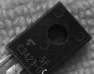
And for the VAS I want some better devices - just scored a few 2SC3423's from fleecebay - we'll see if they turn out to be useable....
I want to re-use my TGM1 amplifiers as they are built and populated so I'm looking to see what approach for TGM4 will be easiest to implement by modifying the TGM1 modules.
And for the VAS I want some better devices - just scored a few 2SC3423's from fleecebay - we'll see if they turn out to be useable....
Attachments
Last edited:
Member
Joined 2009
Paid Member
Oh dear, the Rush Cascode has now been patented
United States Patent US6781459
The US patent system is ridiculous, how can one patent ideas that are public knowledge, also seen with TMC which is patented for second time.
Beware soon Ill be applying for a patent for global negative feedback since noone has patented for a second time.

Yes, Christopher Rush, Englishman, 1964. I note Mr Brown has patented all and every variation of the RC as well, while carefully avoiding attribution to Mr C. Rush. And the TMC addition is a disgrace.
I guess when patent law is dominated by law rather than technology, and PAs are chasing work, then this is what happens.
We really need another Einstein in the patent office.
Hugh
I guess when patent law is dominated by law rather than technology, and PAs are chasing work, then this is what happens.
We really need another Einstein in the patent office.
Hugh
Member
Joined 2009
Paid Member
maybe Einstein was wasted in a patent office.
Well I'm already bored with TGM4 before I even built it; this thread is heading for a dead end. I may return to the use of a Rush Cascode one day if I find the interest in another SS Class AB, but as for the Lender design - it'll remain a simulation.
Perhaps the Chinese are right about the number 4 being inauspicious...
Hi Hugh,
I guess you can patent anything in the USA that does not yet have a patent in the USA yet. They do not look at public domain at all. Look at all the patents of iPod that has been used and forgotten already for years by other cellular manufacturers (Nokia, Samsung, etc). In the USA it is big business and a legitimate way of earning an income from other successful companies or people without having to work for it.
Over here in SA stealing is a legitimate way of earning as well as less costly because it does not involve lawyers.
Last edited:
- Status
- This old topic is closed. If you want to reopen this topic, contact a moderator using the "Report Post" button.
- Home
- Amplifiers
- Solid State
- TGM4 amplifier