The voltage and the phase must be identical for this to be useful. Yes it works but a tiny phase difference in the fundamental between the two signals and they do not "difference" exactly.Could I also look at the "difference" (don't know correct term) between the waveforms? If I would take the original signal of ~1V from soundcard to channel 1 and the amplified signal of ~1-20V from the amp to channel 2, and compared them on scope, would I get something uselful out this way? Or should the voltage of the signals be identical for this to work?
It seems that the optimal bias for these amps are the original 10mV, who would have quessed  . Odd harmonic distortion content rises after this point at all power levels. They have also another 1,36kohm resistor connecting from emitter to somewhere I cannot see. I have not noticed these little resistors before, and I wonder where are they connected to? They are not in parallel with the 0,5ohm emitter resistors.
However I would like to rise the bias current. Would it be possible to lower the emitters resistor's resistance by soldering another 5W resistor in parallel with the originals? I would prefer this so I won't have to desolder 48pcs of resistor off from all amp boards. Would 3,3ohm resistor in parallel with 0,5ohm give me approx 0,263 ohms total, which would double the bias current from sole-0,5ohm-resistor situation?
Regards,
Legis
. Odd harmonic distortion content rises after this point at all power levels. They have also another 1,36kohm resistor connecting from emitter to somewhere I cannot see. I have not noticed these little resistors before, and I wonder where are they connected to? They are not in parallel with the 0,5ohm emitter resistors.However I would like to rise the bias current. Would it be possible to lower the emitters resistor's resistance by soldering another 5W resistor in parallel with the originals? I would prefer this so I won't have to desolder 48pcs of resistor off from all amp boards
. Would 3,3ohm resistor in parallel with 0,5ohm give me approx 0,263 ohms total, which would double the bias current from sole-0,5ohm-resistor situation?Regards,
Legis
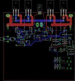
I decided not to use the Toshiba fets in the output and just go with the IRFP240 and 9640. Anyone see any major problems with my board layout. Top sides of the board is a ground plane but I do not have it turned on because it is difficult to see the routing with it on.
Thanks
Thanks
Attachments
Would 3,3ohm resistor in parallel with 0,5ohm give me approx 0,263 ohms total, which would double the bias current from sole-0,5ohm-resistor situation?
Whoops, miscalculation, I would get 0,434R that way. I think I might be better of soldering another 0,5R resistor in series with the original 0,5R emitter resistors to get 0,25R, but is this unoptimal (using two resistors instead of one)?
Think I'd just add that when testing any built or repaired amp, you need to do your first test with NO speakers or load connected, and with some form of current-limited power supplies.
Current limiting could take the form of an SMPS with suitable current limiting, or a linear PSU with some form of ballast resistors in the DC rails. (Lightbulbs can be one cheap form of ballast resistor!)
While running with a current-restricted supply, check that the bias pot works and can be set to give a sensible quiescent current. Also meter the output DC offset, and if it is excessive, find out why. Only when you are happy that everything is under control, connect the unrestricted supply.
Otherwise you are effectively playing Russian roulette, as if anything at all is wrong with your work, you likely have a disastrous blow-up.
Hope this answers the point about bias considerations!
BTW, paralleled FETs need to be matched for similar turn-on voltages, there is no easy way round this. This may mean buying a few more than you actually need.
0,25ohm emitter resistors seem to work a-ok, measured performance took a leap forward as THD dropped due to higher bias current and output impedance decreased.
Slightly silly question, but would direct coupled, meaning no emitter resistors at all, be "asking for it" with an amp that has 12 pair of BJTs? I thought I might try it by shorting all the Re, turning bias pots all the way down, and work my way up from there and monitor the power consumption of the amp. For balancing the bias between the amps and their amp modules I think I would have to resort to temperature readings, or is there some way to measure bias voltage from an amp without emitter resistors?
This is really tempting as it would eliminate distortion, inductance (RF antenna) and resistance (lower output impedance) that the emitter resistors are causing to some extent.
Hi
If bias is set too high then the class A region will be larger and small signals will not be affected by crossover but when the signal exits the class A region the current gain of the complementary pair is reduced causing distortion. This is the effect of Gm doubling. For class AB a compromise must be adhered to. Ideally you would want to maintain a constant conductance across the entire operating region around the current crossover. The real world is not so perfect. The value of Re should be similar to the intrinsic resistance at idle. Also the idea behind the ballast resistors (Re) is to reduce the % difference of the intrinsic resistance between the 'matched' transistors. Leaving out Re would affect the thermal stability and current sharing as well as lessening the continuity of Gm through the crossover region, increasing XO distortion.
If bias is set too high then the class A region will be larger and small signals will not be affected by crossover but when the signal exits the class A region the current gain of the complementary pair is reduced causing distortion. This is the effect of Gm doubling. For class AB a compromise must be adhered to. Ideally you would want to maintain a constant conductance across the entire operating region around the current crossover. The real world is not so perfect. The value of Re should be similar to the intrinsic resistance at idle. Also the idea behind the ballast resistors (Re) is to reduce the % difference of the intrinsic resistance between the 'matched' transistors. Leaving out Re would affect the thermal stability and current sharing as well as lessening the continuity of Gm through the crossover region, increasing XO distortion.
Last edited:
Slightly silly question, but would direct coupled, meaning no emitter resistors at all, be "asking for it" with an amp that has 12 pair of BJTs?
A single pair is OK without emitter resistors so long as the thermal design is good. Multiple pairs, no.
Emitter resistors don't increase the output z by any significant amount, since they are inside the feedback loop.
Agree that on BJTs in class AB, using high quiescent currents doesn't seem to offer any advantage. It's best set just slightly higher than needed to eliminate x-over distortion at very low volumes. If you don't have emitter resistors you can measure the DC supply, subtracting the current drawn by the rest of the cct.
Assuming emitter resistor Re = 'r'e(idle), where 'r'e(idle) is the sum of the intrinsic emitter resistance and the intrinsic base resistance/Beta. The intrinsic resistance is not the same at idle as it is at high conductivity with large signals. Zout for large signals is approximately 'r'e(high conductivity) + Re, which is pretty much just Re as 'r'e for large signals is much smaller. For small signals around the current crossover, both halves of the output stage contribute to the output conductance so Zout ~ ('r'e(idle) + Re)/2. Since at high conductivity 'r'e could be as much as 1/100 of 'r'e at idle, not including the emitter resistors will result in a larger % change of Zout, (Zout and RL form a voltage divider) and thus larger change in Av for the output stage leading to increased distortion. There is more than just thermal stability and current sharing involved with the output emitter resistors in a class AB EF output stage.
If Re is chosen to be equal to 'r'e(idle) then Zout for large signals is closer to Zout for small signals. This is the compromise that all class AB OPS has to deal with. If 'r'e = Vt/Iq, Vt=thermal voltage (Vt ~ 26mV at room temperature), then Re=Vt/Iq. Vq=Re/Iq=Vt. Vq is the voltage across the emitter resistor, VRe. This is a simple basic way to find the optimum bias current and emitter resistors.
If Re is chosen to be equal to 'r'e(idle) then Zout for large signals is closer to Zout for small signals. This is the compromise that all class AB OPS has to deal with. If 'r'e = Vt/Iq, Vt=thermal voltage (Vt ~ 26mV at room temperature), then Re=Vt/Iq. Vq=Re/Iq=Vt. Vq is the voltage across the emitter resistor, VRe. This is a simple basic way to find the optimum bias current and emitter resistors.
Thanks for the answers. I think I'm going to stay "final" at the 0,22 ohms for emitter resistors. I think I will order 12W Mills non-inductive a whole bunch for those, as they are directly in a signal path and there are 24pcs per channel of them. High quality parts at the signal path are always preferable especially if they come in large quantities.
Bypassing emitter resistors with wire was a disaster. After some point the bias literally propelled like a rocket. Luckily I managed to turn off the amp before anything happened. That was bad idea from the start but now I'm one exprerience richer.
This has nothing to do with biasing topic, but I also though to change the output coil damping resitor, which is 10ohm/3W originally, to 2ohm/12W or 1ohm/12W Mills non-inductive type, as it is also in the signal path. I think the 12W is going to be fine. If the resistor would be kept as a 10ohm, it would need to be 15W (2ohm) or 30W (1 ohm) due to similar high end peaking magnitude to highly capacitive loads, but I think by decreasing the resistance the peaking at 40-100KHz region to Hi-C loads is greatly decreased and thus less power is dissipated at the resistor (and the coil). What do you think, and would you get 1 or 2 ohms?
I think that Self recommends 1ohm as it neutralizes the ringing completely, just one tiny overshoot and that's it. 2ohms would be nearly as good I think.
Bypassing emitter resistors with wire was a disaster. After some point the bias literally propelled like a rocket. Luckily I managed to turn off the amp before anything happened. That was bad idea from the start but now I'm one exprerience richer
.This has nothing to do with biasing topic, but I also though to change the output coil damping resitor, which is 10ohm/3W originally, to 2ohm/12W or 1ohm/12W Mills non-inductive type, as it is also in the signal path. I think the 12W is going to be fine. If the resistor would be kept as a 10ohm, it would need to be 15W (2ohm) or 30W (1 ohm) due to similar high end peaking magnitude to highly capacitive loads, but I think by decreasing the resistance the peaking at 40-100KHz region to Hi-C loads is greatly decreased and thus less power is dissipated at the resistor (and the coil). What do you think, and would you get 1 or 2 ohms?
I think that Self recommends 1ohm as it neutralizes the ringing completely, just one tiny overshoot and that's it. 2ohms would be nearly as good I think.
Last edited:
If the output bias is 1080mA, i.e. 1080 bias flowing throw the 12 NPNs and the same 1080mA flowing through the 12 PNPs, then the ClassA current limit of this Push-Pull stage is 2160mA.
The maximum ClassA output power is Ipk^2 * Rload / 2 = 2.16*2.16*8/2 = 18W
10mVre is unusually low for an EF output stage. Is your amp fitted with a CFP output stage?
But, equally, 45mVre is well above an optimal ClassAB bias voltage.
Q.
does the bridged balanced amp have 24 output transistors or 48 output transistors?
If 24, then it must have a 6pair output stage in each balanced half and the 10mVre total bias current is only 120mA for a ClassA current limit of 240mA giving 1/4W of ClassA output.
Hi Andrew,
I don't understand the last Q-part. If there is 10mV voltage drop accross every 24pcs of 0,5R emitter resistors, shouldn't the total bias current be (10mV/0,5R)*24 = 480mA (960mA peak according to Pass?)? Did you calculate the bias current like that the 10mV is the total voltage drop accross one BJT pair, and not accross each emitter resistor?
Now I have changed the emitter resistors to 0,15R, and kept the 10mV voltage drop accross each emitter resistor (20mV per pair), as this voltage drop was best according to THD measurements. This gives approx 1,6A (3,2A peak) total bias current, which translates to ~10,25W / 41W peak, am I right?
Others can answer as well of course.
Regards,
Legis
- Status
- This old topic is closed. If you want to reopen this topic, contact a moderator using the "Report Post" button.
- Home
- Amplifiers
- Solid State
- Biasing Question