"A" & "B"
I believe so, but my pocket doesn't says that. (i'm still a young student with not much allowance) I personally doesn't particular about time, since these things is our passion (SOUL )
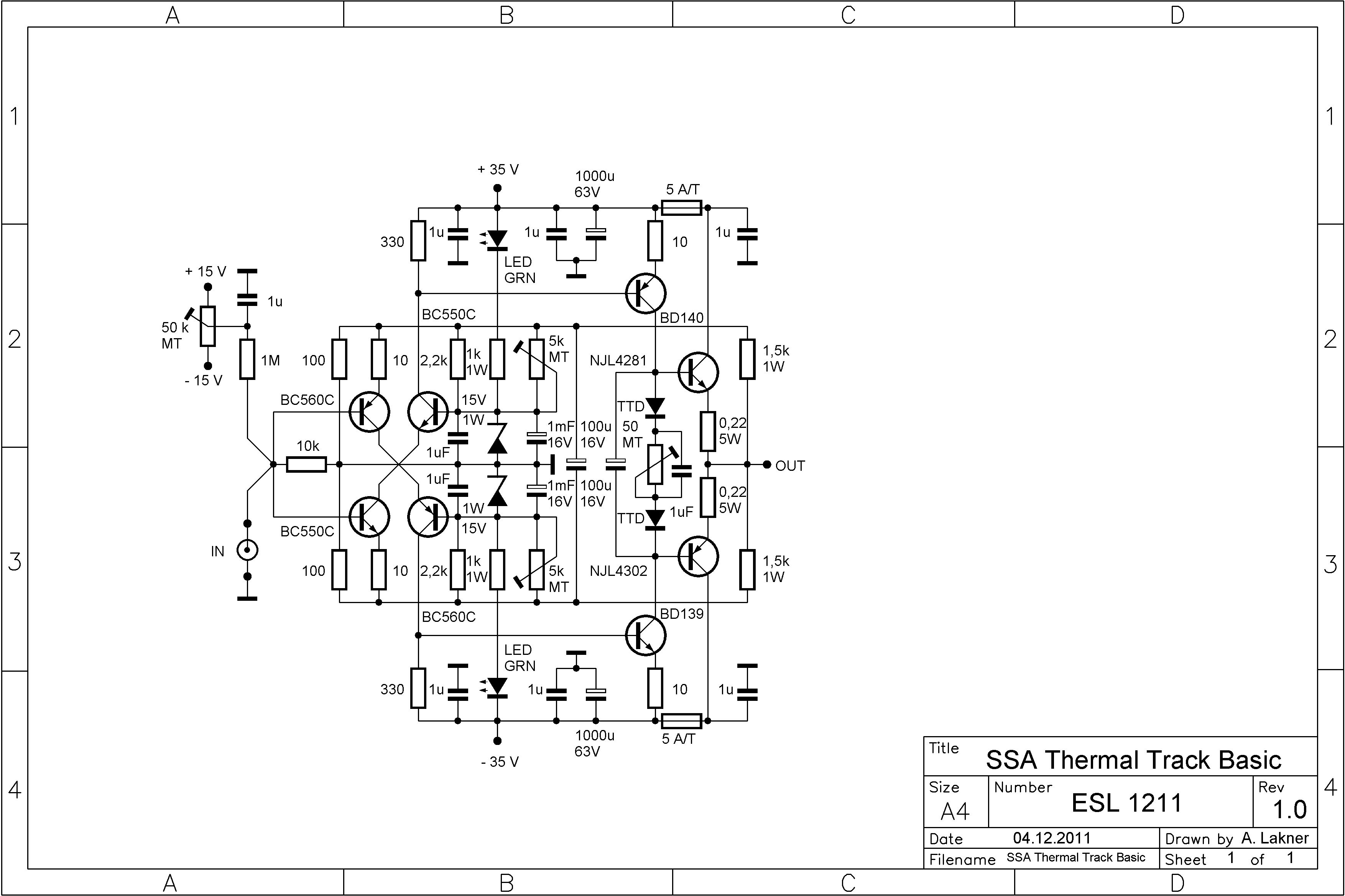
For those input transistor, if you notice carefully, there are "A" and "B", which is cross-connection. I only can do vertical or horizontal line, but not slant line, so I use those for connection. Those they are not connected to ground.There is something I dont understand: how can your Q3, Q4 bases be at +15V and -15V while their emitters are at 0V ?
[edit] Yes, experimenting in real world and listening seems to me the only way to increase his experience and make-it part of yourself. I'm not sure that all this virtualisation gives no good. It saves time, (money) but kill the soul. (Yes, amps had some kind of soul when they were handcrafted)
I believe so, but my pocket doesn't says that. (i'm still a young student with not much allowance) I personally doesn't particular about time, since these things is our passion (SOUL )
esperado,
For your information, it works in reality and doesn't even felt different temperature from ambient.
For Transistor to conduct, they must have potential different. Take an example, Q4 have base on 15V, but on emitter end, in order to conduct, it depends on collector of Q1, which is connected through "B". (Q4's emitter to Q1's collector)
Thus I don't think there is possible way for it to burst, melt or 'flame'(burn).
Forget, just your schematic was not readable and looked (to me) like the two Q3/Q4 emitters where connected on the same line.Thus I don't think there is possible way for it to burst, melt or 'flame'(burn).
I'm agree with you that its not nice ^^ was planning to make a new schematicForget, just your schematic was not readable and looked (to me) like the two Q3/Q4 emitters where connected on the same line.

LC, there is a funny thing on my power supply too. Although it is +-40V but it is only 120VA, means for stereo, only 60VA each channel. With load variation from 2ohm - 16ohm, the maximum voltage swing is only +-20V before my trafo gone heaven. (Hope my calculation is correct)
So i guess the 2SA1707/2SC4487 is still suitable for use ? since I have no hope to reach higher....
This transformer is not really a pearl in a necklace it is more like auxiliary spare wheel in a car. For one channel maybe conditionally acceptable but for stereo amp way out of a good choice. Such power supply will worsen stereo separation, cause unstable behaviour, PSRR of this amp demands low rails ripple but yours will be as Himalayas ...

LC, what i'm thinking is such design as attached.
By using those, I get very high open loop gain and low THD.
The VAS are biased as 0.7mA & 10mA
The driver is biased to 1-2mA & 20mA to Output device.
what could be the good number for C13, which is around the OPS, between the Drivers ?
I intend to change those drivers to the 2SA1707/2SC4487 (didn't do in SPICE because no model.....)
and the OPS change from 0281/0302 to NJL4281/4302. (In SPICE, the number is quite outrages......)
Hope it will turn out into a very nice X.x
Your choice of VAS transistors are not optimum, I'm telling you this at least in 10 posts so this will be my final advice regarding them. Please do not use TO-220 BJT's in VAS. Single VAS transistor has to have minimum 100 Vce and beta more than 300. Cascoded VAS: gain transistor's beta more than 500, casode BJT 100 Vce. Double MJE like in your sch is completely wrong choice for the purpose. I become shivered everytime I see those gorillas in the sensiteve VAS position.

Last edited:
I've got one channel of ThermalTrak Basic built: http://www.diyaudio.com/forums/atta...etrical-amplifier-ssa-thermal-track-basic.jpg
Only significant difference is 2SA1360/2SC3423 for the drivers. Resistor values are as shown, except 2.2R base stoppers for the output devices. Before I fire it up, I could use some guidance on a starting point for the 5K trim pots that parallel the 2.2k resistors into the feedback network. How much current do we want through the zeners, and how much into the feedback network?
Sheldon
Hi Sheldon
Please carefully follow this instructions:
- set 50k MT trimmer in the middle position, this one nulles input offset to zero, so there is no difference in the output DC if you shortened input with wire to GND or if the input is completely opened
- please change both 2,2 k resistors to 5,6 k and start with max resistance of both 5 k MT. These two defines VAS bias current to app. 10-12 mA and at the same time zero output DC offset.
- set 50 ohm MT to zero at start, this one defines output bias current to app. 150 mA
Your choice of VAS (driver) transistors is very good, maybe these two will need small 10-22pF local feedback ceramic caps (Miller compensation) between their collector to base pins (as close as possible) but only in a case if you notice some oscillations at the output.
Last edited:
wow, mine is himalayas ? X.x i'm going to get another Transformer later I guess..... I will get another transistor as you said to fit.This transformer is not really a pearl in a necklace it is more like auxiliary spare wheel in a car. For one channel maybe conditionally acceptable but for stereo amp way out of a good choice. Such power supply will worsen stereo separation, cause unstable behaviour, PSRR of this amp demands low rails ripple but yours will be as Himalayas ...
Your choice of VAS transistors are not optimum, I'm telling you this at least in 10 posts so this will be my final advice regarding them. Please do not use TO-220 BJT's in VAS. Single VAS transistor has to have minimum 100 Vce and beta more than 300. Cascoded VAS: gain transistor's beta more than 500, casode BJT 100 Vce. Double MJE like in your sch is completely wrong choice for the purpose. I become shivered everytime I see those gorillas in the sensiteve VAS position.
The MJE in the schematic was substitute X.x it is indeed an gorilla instead of cheetahs.... If in cascode arrangment, I use MJE as cascode BJT, and the 2SA1707/2SC4487 temporarily, is it fine ? (seems the transistor have insufficient beta)
How much current do we want through the zeners, and how much into the feedback network?
Sheldon
Hi Sheldon
To rule out any misunderstanding you have to measure three things only:
- output voltage must be measured with oscilloscope to see if you have any oscillation or DC offset. Whatever you do with trimmers, never exceed output DC over +/- 1 V
- voltage drop across 10 ohm VAS emitter resistor must be 100-120 mV optimally, in this case your VAS bias current will be 10-12 mA and input bias will be automatically around 2,3 mA
- voltage drop across 0,22 ohm output emitter resistor must be 33 mV optimally, in this case output bias current will be 150 mA
Regards Andrej
Last edited:
- set 50k MT trimmer in the middle position, this one nulles input offset to zero, so there is no difference in the output DC if you shortened input with wire to GND or if the input is completely opened
- please change both 2,2 k resistors to 5,6 k and start with max resistance of both 5 k MT. These two defines VAS bias current to app. 10-12 mA and at the same time zero output DC offset.
- set 50 ohm MT to zero at start, this one defines output bias current to app. 150 mA
Your choice of VAS (driver) transistors is very good, maybe these two will need small 10-22pF local feedback ceramic caps (Miller compensation) between their collector to base pins (as close as possible) but only in a case if you notice some oscillations at the output.
Thanks Andrej,
Check, on the input trimmer.
Will find some 5.6k or close. Setting the trimmers to max resistance makes an easy starting point, with defined minimum. I have been curious though; don't these rail trimmers make the input trimmer redundant? Or is trimming the output offset with these respond differently to changing conditions, than adjusting the input trimmer?
Check on the bias spreader trimmer to zero.
To rule out any misunderstanding you have to measure three things only:
- output voltage must be measured with oscilloscope to see if you have any oscillation or DC offset. Whatever you do with trimmers, never exceed output DC over +/- 1 V
- voltage drop across 10 ohm VAS emitter resistor must be 100-120 mV optimally, in this case your VAS bias current will be 10-12 mA and input bias will be automatically around 2,3 mA
- voltage drop across 0,22 ohm output emitter resistor must be 33 mV optimally, in this case output bias current will be 150 mA
Easy enough, thanks.
Currently I have 0.1R output emitter resistors. I had left those in there from my experiments with Mihai's (Roender) output buffer. He recommended a voltage drop across the emitter resistor of about 18mV for the optimum class B bias. Though he did recommend that if a different value is chosen, it's better to be higher than lower. I had thought that this value is a property of the particular output device. You are recommending about double that. I can do either way.
BTW, my application for this amp with be driving the mid/highs for a 100dB speaker (8 Ohm). I won't need more than 20W for even the highest transients, at live levels. Most listening will be much less. So for normal to somewhat loud, it would be nice to live in class A.
Sheldon
Hi Sheldon
Base currents of the input transistors are not equal so this difference always causes voltage drop on input 10 k resistor therefore some DC to be present, usually few mV. So if you connect the source which has zero DC on its output (same if you connect input to the ground) the output of the amp will go to DC level of voltage gain multiply few mV, which is undesirable. 50 k MT input offset trimmer is serving to cancel this by supplying (via 1 M series resistor) the current to the bases of input transistors needed to compensate base currents (sum of all three currents is zero - Kirchhoff's current law) thus in effect the voltage drop on 10 k input resistor is zero.
Base currents of the input transistors are not equal so this difference always causes voltage drop on input 10 k resistor therefore some DC to be present, usually few mV. So if you connect the source which has zero DC on its output (same if you connect input to the ground) the output of the amp will go to DC level of voltage gain multiply few mV, which is undesirable. 50 k MT input offset trimmer is serving to cancel this by supplying (via 1 M series resistor) the current to the bases of input transistors needed to compensate base currents (sum of all three currents is zero - Kirchhoff's current law) thus in effect the voltage drop on 10 k input resistor is zero.
Last edited:
You are recommending about double that. I can do either way.
I recommend 33 mV across 0,22 ohm, resulting in 150 mA of bias current.
Roender recomment 18 mV across 0,1 ohm, resulting in 180 mA of bias current.
Both approximately the same.
Yes, there is an adequate response in harmonic distribution structure of the output signal if you change the bias current level. Normally more problematic is underbiased output than A class bias, but sonical reports are in favour in choosing optimum bias level, usually 150-200 mA per output device.
On most of my amps with powerfets, i used to find 150ma the best crescent current for each active device.(as i use two // ones, on my amp, i set 300ma).So for normal to somewhat loud, it would be nice to live in class A.
It is enough to get Class A at normal levels, to maintain a good temp on the output devices (too cold sound harsher) and i never noticed any listening improvements in upper currents.
The amp goes faster in temp, and that is an advantage too.
Hi Esperado
SSA second channel built, powered on to full supply, no problems at all. Since the main heat sink Fischer SK-157 has 0,28°K/W I can bias up tp 500 mA per output device (1A bias sum) ending at 120 W idle dissipation per channel. This would get me 33,6°K of extra temperature plus ambient's 22°C, resulting in 55°C final heatsink temperature. But the benefit is I will get a pure A-class up to 20 W/20 ohm for my high impedance horn speakers. I know such heatsink temperature is absolute reasonable maximum, so maybe I'll go to 400 mA per output device, gettin' away with some 50°C.
Otherwise channel sings music nicely, still no hiss, hum or any noticable noise at any speaker's cone so all in all both channels are ready to go in a case. I also connected/disconected live signal RCA at full opened channel, also stop RCA at only live pin connected, GND not touching the RCA and there was no instability or any kind of oscilation. Amp just picked 50 Hz and 50 kHz scope LCD monitor freq and amplified them. I also connected SONOS Connect (Zone Player 90) which has few mV of 200 kHz sine plus 10 MHz spikes (3 periods of damped sine) every 4 us at idle (volume on min) and this signal was also amplified at the output of the amp. First I thought the amp is oscillating but measuring the input revealed the poor and sad analog output of this SONOS network player ...
Last edited:
Yes, there is an adequate response in harmonic distribution structure of the output signal if you change the bias current level. Normally more problematic is underbiased output than A class bias, but sonical reports are in favour in choosing optimum bias level, usually 150-200 mA per output device.
Set at 175mA in mine.
Hi Esperado
SSA second channel built, powered on to full supply, no problems at all. Since the main heat sink Fischer SK-157 has 0,28°K/W I can bias up tp 500 mA per output device (1A bias sum) ending at 120 W idle dissipation per channel. This would get me 33,6°K of extra temperature plus ambient's 22°C, resulting in 55°C final heatsink temperature. But the benefit is I will get a pure A-class up to 20 W/20 ohm for my high impedance horn speakers. I know such heatsink temperature is absolute reasonable maximum, so maybe I'll go to 400 mA per output device, gettin' away with some 50°C.
Otherwise channel sings music nicely, still no hiss, hum or any noticable noise at any speaker's cone so all in all both channels are ready to go in a case. I also connected/disconected live signal RCA at full opened channel, also stop RCA at only live pin connected, GND not touching the RCA and there was no instability or any kind of oscilation. Amp just picked 50 Hz and 50 kHz scope LCD monitor freq and amplified them. I also connected SONOS Connect (Zone Player 90) which has few mV of 200 kHz sine plus 10 MHz spikes (3 periods of damped sine) every 4 us at idle (volume on min) and this signal was also amplified at the output of the amp. First I thought the amp is oscillating but measuring the input revealed the poor and sad analog output of this SONOS network player ...
Input layout should be taken with care on All wideband amps.
If such a 10Mhz signal is to large you Will end up destroying the output devices. Parasitic caps (even af few nf) Will pull a lot of current and destroying the silicon.
In my amps i Pick up the rf from the oki/metcal solderiron.
Just be carefull.. Nice to hear it works well for you.
I have criticism your layout but it looks good when build.
i just hope you dont need to repair it!! LC, nice to heard your amplifier is done.
Last night, i changed the simple ones i have built, the VAS (MJE 13034/35) into 2SA1707/ 2SC4487, working normally.
After trying to listen, it seems the sound has degraded (a bit blur than previous), not sure about yesterday's ear condition, so going to test listen today later. Any idea what could cause that ?
Set at 175mA in mine.
I know this is optimal setting but the heatsink is barely warm at this bias level. I would like to squeeze out the best of these high performance heatsinks. At 500 mA quiescent current per one output device will there be degradation of sound in any meaning? I never had an amp with such high bias so I am quite enthusiastic to have one of these.
LC, nice to heard your amplifier is done.
Last night, i changed the simple ones i have built, the VAS (MJE 13034/35) into 2SA1707/ 2SC4487, working normally.
After trying to listen, it seems the sound has degraded (a bit blur than previous), not sure about yesterday's ear condition, so going to test listen today later. Any idea what could cause that ?
2SA1707/ 2SC4487 having Ucemax=50 V so I assume there is an issue with this parameter since everything else looks pretty good in specs. I said already try to get your hands on 2SA1209/2SC2911 and use them as cascodes to BC550c/BC560c.
- Status
- This old topic is closed. If you want to reopen this topic, contact a moderator using the "Report Post" button.
- Home
- Amplifiers
- Solid State
- Simple Symetrical Amplifier