Hi igor0203
Yes of course, maybe even GB if there will be some interest shown here.")
I think this won't be a problem...

Just a little teaser
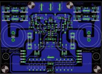
The SSA BIGBT HP PCB is almost ready to be published. I will be the first one to build this version on a new shiny PCB which will be prepared by master Alex. Hardly wait to get a Christmas gift

Hi Andrej,
That's awesome!!!
Put me on your list for the GB.
Hi igor0203
Yes of course, maybe even GB if there will be some interest shown here.
Ohhh yes...sounds great, I might be in also so keep us posted.
BTW, I'm curious about the implemtation on those boxes of yours for the BIGBT's
can you show us the inside? need the power resistors be non inductive? its only 0.22 Ohms so I think it wont matter at all.
Cheers, Tony
N & P-BIGMT ?
LC,
Hurry is never good at all, You are right, I did foreseen the most important details of Yours suggestions, hopefully now solved + I add an option for possible realization of Yours BIGMT module in post #458.
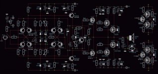
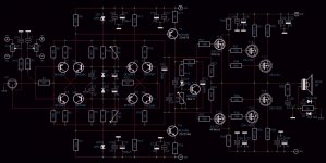
I hope that I redraw it correctly... Yours proposed SCH, please correct it if any errors. This is is also what I wonder to try, would the output be similar near to the rails as with this present OP stage ?
I have a 750W toroid with 4 separate sec. winding 30V AC. This would be enough for driving low imped. speakers.
Any additional kind suggestion for the best sound outcome from this simple SSA bal-fet version would be much appreciated.
Thank You,
Hi Sound Rays
The same issues remains with T9,10,13,14 as before.
Please read my corrections again.
Regards, Andrej
LC,
Hurry is never good at all, You are right, I did foreseen the most important details of Yours suggestions, hopefully now solved + I add an option for possible realization of Yours BIGMT module in post #458.
I hope that I redraw it correctly... Yours proposed SCH, please correct it if any errors. This is is also what I wonder to try, would the output be similar near to the rails as with this present OP stage ?
I have a 750W toroid with 4 separate sec. winding 30V AC. This would be enough for driving low imped. speakers.
Any additional kind suggestion for the best sound outcome from this simple SSA bal-fet version would be much appreciated.
Thank You,
Attachments
Hi Sound Rays
Khmm, new sch of yours, khmm, new comments (cannot just say confirmed ):
):
- correct T1, T4, T6, T7 to BC560C, it's a must
- correct T2, T3, T5, T8 to BC550C, it's a must
- if you will use T13 as 2SK216 and T14 as 2SJ79 than T11 is BC550C mounted on a PCB (not on the main heatsink), because of the negative tempco of 2SK216/2SJ79. If you will use IRF's as drivers than T11 is BD411 on the heatsink, period.
- T15, T17 are P-channel mosfets, so you must reverse diode orientation. It should be exactly the same as it is drawn inside T14 symbol (the same P-channel mosfet). Please Sound Ray, electronics is suppose to be very exact science and you have major discrepancy here.
- T15, T17 are 2SJ162 not 2SJ62, correct it please
- omitt D3, D4 completely, you don't need them because mosfet symbol shows you that these diodes are already incorporated inside both mosfet channels
- C26 is 0,1 uF
- you will need extra P1, C1, Rx for the negative input DC offset calibration
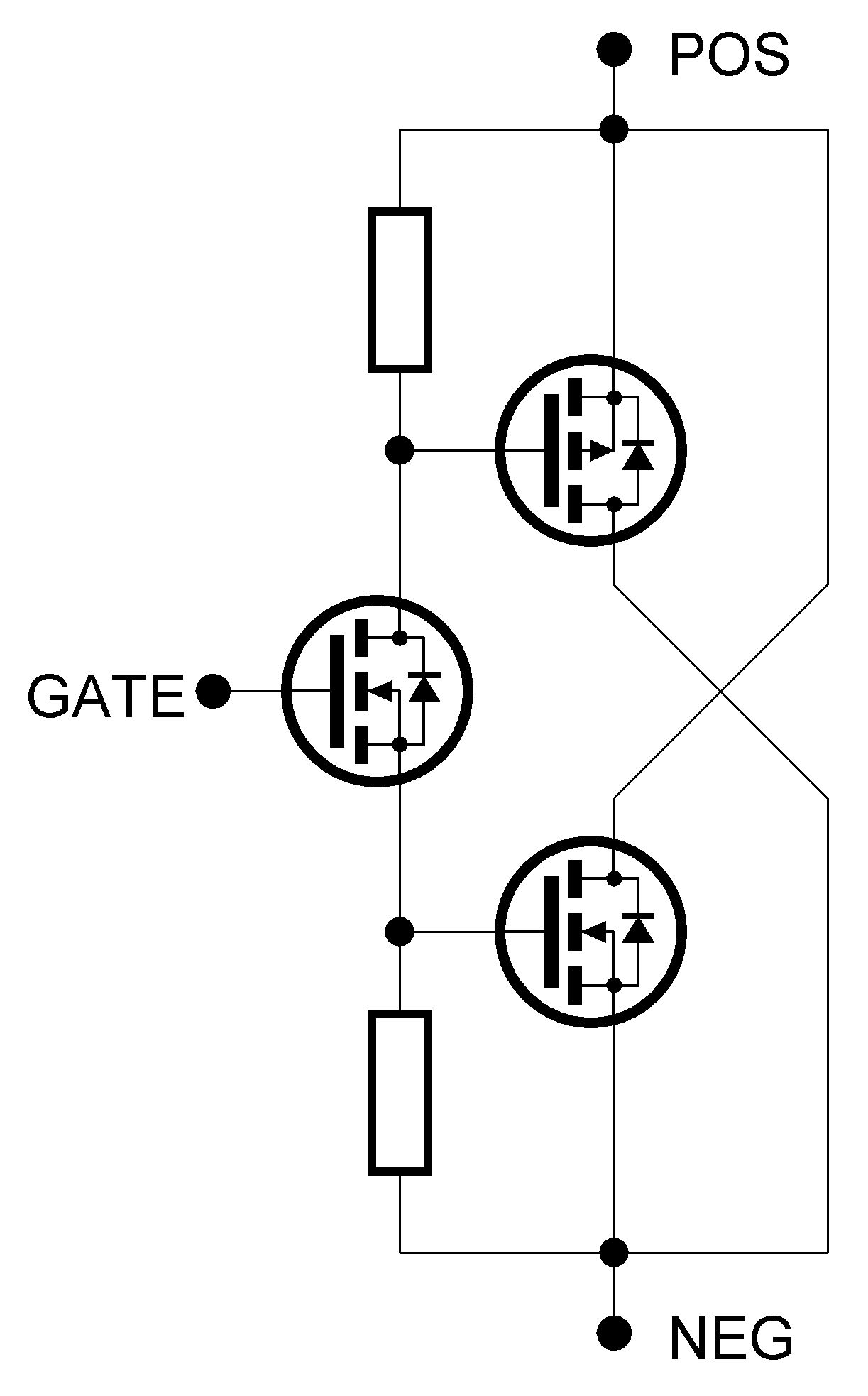
Regarding all mosfet BIGBT (Balanced Insulated Gate Bipolar Transistor) my opinion is that it can work but very hardly to be balanced ever, even if you trimmed R38, R39 to 50-50 output drain currents. If it would ever work than also the name would change into BIGMT as you already stated. Bipolar transistors works as a current gain devices so inside BIGBT, mosfet driver runs only one base current for both BJT's all the time and if hFE's are equal, thus naturally forces outputs to the exactly equal collector currents. By mosfets as balanced outputs, Vgs among both channels are so different through the whole range of transconductance, that balanced operation would be simply mission impossible.
Please repost all-corrected sch for the last inspection, regards, Andrej
Khmm, new sch of yours, khmm, new comments (cannot just say confirmed
):- correct T1, T4, T6, T7 to BC560C, it's a must
- correct T2, T3, T5, T8 to BC550C, it's a must
- if you will use T13 as 2SK216 and T14 as 2SJ79 than T11 is BC550C mounted on a PCB (not on the main heatsink), because of the negative tempco of 2SK216/2SJ79. If you will use IRF's as drivers than T11 is BD411 on the heatsink, period.
- T15, T17 are P-channel mosfets, so you must reverse diode orientation. It should be exactly the same as it is drawn inside T14 symbol (the same P-channel mosfet). Please Sound Ray, electronics is suppose to be very exact science and you have major discrepancy here.
- T15, T17 are 2SJ162 not 2SJ62, correct it please
- omitt D3, D4 completely, you don't need them because mosfet symbol shows you that these diodes are already incorporated inside both mosfet channels
- C26 is 0,1 uF
- you will need extra P1, C1, Rx for the negative input DC offset calibration
Regarding all mosfet BIGBT (Balanced Insulated Gate Bipolar Transistor) my opinion is that it can work but very hardly to be balanced ever, even if you trimmed R38, R39 to 50-50 output drain currents. If it would ever work than also the name would change into BIGMT as you already stated. Bipolar transistors works as a current gain devices so inside BIGBT, mosfet driver runs only one base current for both BJT's all the time and if hFE's are equal, thus naturally forces outputs to the exactly equal collector currents. By mosfets as balanced outputs, Vgs among both channels are so different through the whole range of transconductance, that balanced operation would be simply mission impossible.
Please repost all-corrected sch for the last inspection, regards, Andrej
Last edited:
I have a 750W toroid with 4 separate sec. winding 30V AC. This would be enough for driving low imped. speakers.
Thank You,
750 VA/4 x 30 V transformer would satisfy the power consumption of two channels (stereo amplifier) for 4 ohm speaker loads. Lower speaker impedance than that would demand more transformer's VA. Let say 2 ohm speaker loads doubles the power needs into 1,5 kVA and so on ...
Last edited:
Hi Andrej,
That's awesome!!!
OK thanks, confirmed

Hi Sound Rays
Khmm, new sch of yours, khmm, new comments (cannot just say confirmed
Please repost all-corrected sch for the last inspection, regards, Andrej
LC,
Thank You for Yours really generous and patient support, my old eyes and late night brains are hardly correlated . . .
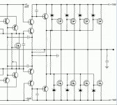
I did the changes and will skip the mission impossible, as You enlighten me the chances are really low. I found on a web a similar Mos OP of Mr. Bora design and is to be a good sounding one, maybe interesting to try that OP stage latter. For my the very first try this would be it, maybe also a conventional OP Stage for comparing the real sound difference between the two and chose the most natural one
Thank You,
Attachments
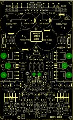
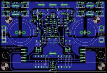
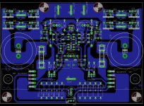
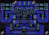
Just one, to make-it the way we can cut the printed circuit it in two parts: power supply and amp. Several reason on my point of view: I allways prefer ti share the same power supply for both channels for stereophonic image stability , and i prefer stabilized ones, as i previously mentioned for sonic quality. Last, some people would like to upgrade their existing amp, keeping their actual power supply ?What do you think about this one boys? Are we slowly getting there? Any suggestions?
Just my two cents.
What do you think about this one boys? Are we slowly getting there? Any suggestions?
If not seperate as Esperado suggest, i would suggest more room for the capacitor area...
May-be this can reduce a little distortion. (see around output)Don't hesitate to comment It.
Attachments
- Status
- This old topic is closed. If you want to reopen this topic, contact a moderator using the "Report Post" button.
- Home
- Amplifiers
- Solid State
- Simple Symetrical Amplifier