I am not pedantic, but still you are wrightif you want help then post accurately !!!!!
again my mistake in prefix -0.4V on bc550c side
Look Josip this design is very simple and also symmetrical, so if you read +V on positive side of the sch there should be the same -V value on the mirror side.

Beside that Vbe of the input pair should be 0,6V for each transistor and voltage across 10ohm emitter resistor should be 45mV each (4,5mA through 10 ohm). So if Vbe is 0,4V at BC550C and 0,35V at BC560C these transistors are completely off. There is probably no supply current through 1k from +/-15V to feedback loop. Every transistor now is currently off. Check the voltages across all resistors (not referenced to GND but from one pin to another pin of a resistor and show us) so we will know which currents are too low.
Be precise with values, polarity and marking, otherwise I can not help.
May i suggest you to open a separated thread about your problem ?I am not pedantic, but still you are wright
Josip,
You better write all voltages on the schematic. This is the way to do some troubleshooting. Put the black lead of your voltmeter to common ground (star or whatever) and take the voltage measurements at all nodes of the schematic.
Then post the schematic and people (or better LC) can send you a PM. This way it will not take pages of this thread.
I personally think that your input is probably OK (at 0.4V B-to-E transistors are already conducting), what I suspect is your output stage. Are your IRF transistors measurements correct? 31,5V to both drain and source?! If yes, they are nicely shorted
May i suggest you to open a separated thread about your problem ?
OK no problem but last question? voltages on Vbe transistor is changing but very little turning 1K trimmer
OK no problem but last question? voltages on Vbe transistor is changing but very little turning 1K trimmer
I do not know does this has something to do with biasing but I changed 1K resistors to 2.7K to get 28dB gain
I rounded them up in the post #785http://www.diyaudio.com/forums/solid-state/193923-simple-symetrical-amplifier-79.html
I rounded them up in the post #785http://www.diyaudio.com/forums/solid-state/193923-simple-symetrical-amplifier-79.html
Not precise link here is better #785http://www.diyaudio.com/forums/solid-state/193923-simple-symetrical-amplifier-79.html#post2709316
Last edited:
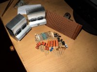
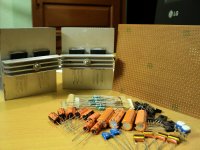
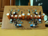
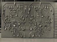
Yes Shaan I like it a lot, very nice layout on vero board, almost as it would be the real PCB. I'm sure the real one wouldn't differ much from this layout cause components are at just the right positions. 
Now I know you are very experienced DIY builder, I also saw your previous amps on vero boards, you have the knowledge and skills, so I think this one would be a piece of cake to make the music play. Also if there will be some issues we will find the way out easily. In the mean time bigun started to sim his TGM5 amp and came out with thermal stability solution for Vbe multiplier which can also be used here if needed. So be confident and go on, others will be here to watch and share the pleasure. Regards, Andrej
Now I know you are very experienced DIY builder, I also saw your previous amps on vero boards, you have the knowledge and skills, so I think this one would be a piece of cake to make the music play. Also if there will be some issues we will find the way out easily. In the mean time bigun started to sim his TGM5 amp and came out with thermal stability solution for Vbe multiplier which can also be used here if needed. So be confident and go on, others will be here to watch and share the pleasure. Regards, Andrej
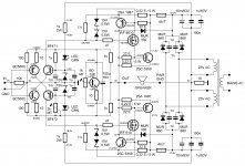
Thanks Lazy this will helpHere is SSA BIGBT Basic schematic equiped with orientational voltages for troubleshooting purposes.
Lucky troubleshooting.
SSA BIGBT Basic Voltages
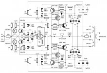
I was asked to publish also the original schematic with marked voltage points for 24V AC supply and here it is.
Here is SSA BIGBT Basic schematic equiped with orientational voltages for troubleshooting purposes.
Lucky troubleshooting.
I was asked to publish also the original schematic with marked voltage points for 24V AC supply and here it is.
Attachments
Yes Shaan I like it a lot, very nice layout on vero board, almost as it would be the real PCB. I'm sure the real one wouldn't differ much from this layout cause components are at just the right positions.
Now I know you are very experienced DIY builder, I also saw your previous amps on vero boards, you have the knowledge and skills, so I think this one would be a piece of cake to make the music play. Also if there will be some issues we will find the way out easily. In the mean time bigun started to sim his TGM5 amp and came out with thermal stability solution for Vbe multiplier which can also be used here if needed. So be confident and go on, others will be here to watch and share the pleasure. Regards, Andrej
Thanks for the kind words LC. I hope my SSA will run without any problems; it's finished and ready to be tested. The only concern I have is the 2k2 pot, which is not multiturn and I could not find a MT pot here. So, maybe, I'll need a servo after all... or maybe not, depending on the pot's influence on the offset.
Thanks for visiting my vero-thread, if you have some old vero designs in archive please post them there.
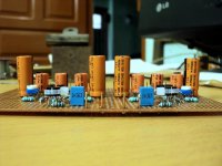
Shaan, I enjoy your approach to reinforce heat sinking with those front small sinks!
Thanks. The idea came to me from Rod Eliott.
Twice the effect with half the holes. Dear shaan,
Those Heatsinks look nice! Are they available anywhere in India? Can you give me the source in India for the Semiconductors also?
--gannaji
I found them in Kolkata chandni market; the old/used equipment sellers lane, for one-fifth the retail price! These are AMD cpu heatsinks and they can dissipate 100watts with medium air flow. I plan to use them in SSA with a thermo-fan control for the fans.
All the semiconductors used in SSA are available at Nahar Electronics in Chandni market Kolkata. They are very mature suppliers and everydbody knows their shop location, ask anyone in chandni and you'll get there.
Last edited:
Nice built Shaan
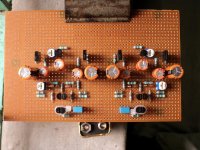
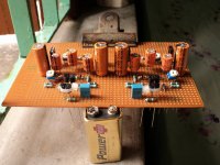
No, cascode BJT's doesn't have to be thermally coupled because their hFE/temperature tracking won't change input collector current. As I see in the pic they are in correct position.
Be careful with start-up procedure minimum bias, fuses/current limiting resistors etc. Please connect output mosfets to PCB with shortest wires as possible.
Good Luck & Enjoy.
- Status
- This old topic is closed. If you want to reopen this topic, contact a moderator using the "Report Post" button.
- Home
- Amplifiers
- Solid State
- Simple Symetrical Amplifier