Hi guys
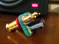
Here's my output binding posts with DC sense circuit.
clever thingie
")
Attachments
Thanks Nico. The hardest thing was to decide which schematic to pick to suit my needs than after it is just pleasure in making it happen. It is still on going process since I await to get the metal case, finish the second channel and make final assembly. I'm really enjoying every single bit of doing this amplifier, especially awaring how it will looks and sounds at the end.
Regards, Andrej
Regards, Andrej
clever thingie
Yeah, I thought it belongs there naturally, since these are the last pins of the amp where we should be certain there is no DC or at least knowing it and response adequately.
Great, but I also like the K+Hs in the background.
Khhh khmm K+H O300 they are.

Yeah, I thought it belongs there naturally
with a small 'reserve/issue', that you will need to 'route' a power supply wire to output terminals....and sense wire, etc, or ?

Andrej, I don't exactly know which circuit you are using for protection. But when DC is sensed at the output 'pins' and the output is cut off and rails voltages colapse, does the latter situation continue till it is manually reset, or does it depend on DC sense for sustaining the protect action? If the second situation is true, the moment the output is cut off, DC sensing is lost, the circuit gets reset and DC is sensed again. This action will go on repeating as long as DC is sensed.
Which is precisely the reason why, in circuits which use a relay for output protection, the sensing is done at a point prior to the ouput switching reeds of the relay. Ofcourse, you situation may be different.
Which is precisely the reason why, in circuits which use a relay for output protection, the sensing is done at a point prior to the ouput switching reeds of the relay. Ofcourse, you situation may be different.
Andrej, I don't exactly know which circuit you are using for protection. But when DC is sensed at the output 'pins' and the output is cut off and rails voltages colapse, does the latter situation continue till it is manually reset, or does it depend on DC sense for sustaining the protect action?
Hi Jayaraj
SSA Soft Start PCB has also 12V protection input (C7, C8 pins) which is triggered from left or right channel's DC sense circuit located at output binding posts. When unwanted DC on amp's output is sensed, protection circuit instantly turn off both channels, 12V remote out voltage on pin C5, C6 drops to zero (amp goes to high Zout mode), shuts down the power supply to both channels, turn on red protection LED on the back panel and breaks small 160 mA power relays supply fuse located on SSA Soft Start PCB, which means the situation is irreversible until someone checks both amp's channels functionality and replace 160 mA fuse. +/-1,2V or higher DC potential on amp's output situation is serious malfunction so it must be treated accordingly.

Does anyone have a Black and White PCB design shown in Post #559, for toner transfer method? Thanks.
Yes, Alex has it.
Correctly and because of that reason, DC protection is mandatory here, 75mV DC from a source in this manner is the upper limit. I wonder if this level of DC coming from any properly designed and working source is even possible-permitted, mhmm?
Not permitted, but it is an accident not in the amp itself. So blowing a fuse is not very practical, could be a resetting relay, but still effective in any rare case.
Hehe blowing the fuse is an optional choice. One can choose if this small fuse is blown (permanently off state) or not (higher fuse value) in a case of a failure. Anyway protection goes to power standby state and reseting is performed simply with re-powering by pressing front panel's button.
VAS stable bias ?
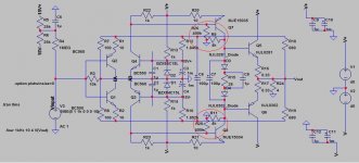
About last time problem I encounter, that the VAS temperature is hard to rise and give low bias voltage, etc. Changing heatsink only helps a little, but still have some duration on heating up. So I found another resolution, but not in audio section, so I'm wondering is it fine with this arrangement.
It is called : "emitter-feedback" bias technique or so..... I have integrated into my VAS, as a red circle area in attached picture.
If i'm not wrong, it have some kind of local feedback, so it significantly reduce the variation of current as temperature changes.
LC, could you help me see is it ok ? according to the schematic i posted, The VAS is idle at 16mA.
Attachments
When compensated to give just a tiny rise before roll off into 8R they perform quite close
SSA is a little more stable perhaps - slew rate was similar at about 800V / uS
Hard to say in spice about distortion but SSA seems to be similar to SMA but with much less OLG !
I will now build my SSA to make a listening comparison
I would be interested in your comments on this version of your design.
I look forward very much to hear this nice amplifier
Last edited:
- Status
- This old topic is closed. If you want to reopen this topic, contact a moderator using the "Report Post" button.
- Home
- Amplifiers
- Solid State
- Simple Symetrical Amplifier