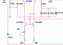
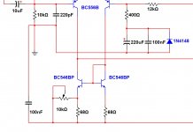
Use rail resistor because they are protection ...
They limit current.
Then adjust to read 100mA each rail.....reading voltage drop over series protective resistor.....when this resistor is 100 ohms, then the reading is 10 volts.
To obtain the current divide the voltage expressed in volts by the protective series resistance expressed in ohms .... this way you can use other resistor values as protective resistor... if you decide to use 47 ohms (because you may have it and wanna use it), then the voltage drop will be 4,7 volts.
After this previous adjustment you go to measure voltage drop over power emitter resistors.. the ones connected into the output power transistors....and now you should adjust your bias trimpot in order to read 1 milivolt there.
Then remove protective resistors and enjoy your amplifier.
Matched transistors does not produce high offset numbers...use matched units and accept your offset as normal till 25 miivolts.
having big off set....big numbers of Dc milivolts in the output then search for errors in your circuit.
After bias adjustment, then remove protective resistors and enjoy your amplifier.
regards,
Carlos
Hi Carlos, merry christmas belated everyone. From your last post you must be a mind reader because I am just getting ready to adjust the bias of my dx I built last summer and put on the shelf till i had time to finish, and I opened up this morning to look how to do it. Will send some pics when it is up and running. Received boards from Byron they look real nice but this looks like next year's project. Best to all, John
Thank you folks...dear Evette and dear John Geneva.
This biasing procedure seems to be a helping hand.... many folks like the stuff.... and i love to help
About off set
We call off set some remaining voltage that appear in the output line... there we must have zero or a couple of milivolts..when the amplifier correctly balanced.... this off set voltage appears with the speaker connected or with the speaker disconnected..better not to connect to work in the safe side.
The output line goes to the positive speaker terminal, and the other terminal goes to the ground...so..if we have a couple of volts, for instance 2 volts, then the voltage will create a current that gonna cross the speaker coil while going to the ground...if your speaker is 4 ohms, then by the ohms law you see that you gonna have 500 miliamperes. This has a consequence.... this current crossing the coil produces heat and also moves the speaker upwards or downwards depending the remaining voltage polarity.... this way the speaker will be out of the center position, being easier to reach the maximum inward or outward movement...this distorts the sound and heat up the output power transistors and speaker coil.
You see... 500 miliamperes is 0.5A.... and by power calculation that is voltage multiplied by current, we have 2 multiplied by 0.5 and this is 1 watt or heat generated.... waste or energy and we go driving the speaker to be out from it's resting position...bad thing when off set is so big this way.
It is bureaucratically considered that 1 to 25 milivolts is fine and does not need any adjustment...factories accept amplifiers having off set within this range.... you can calculate the power....let's say 0.025V goes squared and divided by 4 ohms.... this is the power .... 0.000156W or 156 miliwatts.... really this will not bother the output circuit and will not move the speaker out from the resting position and will not harm..... maybe you will listen a small click when powering the amplifier because this small voltage moving the speaker cone.
Now imagine you have 70 milivolts Dc in the output..... this is not that important also... calculation says we gonna have one point 2 miliwatts.... this is not important too.
Differential transistor mismatch is what usually causes the off set.....usually we have 1 to 5 milivolts when transistors are matched... resistors also plays a little, as they have tollerances ... value is never exactly the value printed in the colour strips. Other transistors produces off set too, but the ones can make a mess are the input differential pair.
We can adjust this tweaking the resistors we have connected to the differential colector, in special de first one can be tweaked... a little bit dangerous as i do not suggest you to use trimpot...or at least i do not suggest you to face the risk to open the circuit by accident or to short there...as you may face huge output voltage unballance.... we can keep the resistors installed into the current sinks...these small values of 56, 68,82 or 100 ohms you see down the colector, or down the current sink transistors you have in contact with the differential transistor colectors.... there you can install resistor in parallel in order to reduce the combined resistance, also you can use a trimpot to tweak.... as you know resistances in parallel reduces the resistor total value...say...the combined value is smaller than the smaller resistor value you have within these combined pair of resistors..... sometimes you have to increase, and them a trimpot in series, a 50 ohms or 100 ohms trimpot in series with the former resistor... now combined in series increasing the total resistance, will also change the off set value that can be negative or positive in milivolts and you can reduce it to zero if you want....i do think you should not bother yourself with that...but if you want...do it.
Yes, there are other methods to ballance.... controling the resistors you have in the differential pair emitters..there you can have a 220 ohms trimpot, sometimes 100 ohms trimpot..and then you can adjust...and there are other methods too...we choose the one we like.
regards,
Carlos
Attachments
Last edited:
I was informed by a builder that he could listen a humming noise
I was informed by a builder, that he could listen a humming noise, a very low level hum, when he put his ears nearby the speaker.
This amplifier is very well filtered in the earlier input circuits to avoid this...also uses a lifted ground that also reduces noises from the supply.... i have made tests and i could not listen noises..so, i suppose that builder is picking up noises from other nearby sources, or transformers, or mains wiring, or input cable shield, or missing lifted ground connection, too much sensitivity, noise from the audio source, missed rail filter condensers after the rail diodes or several other human mistakes.
Well... even sensitivity i am using a huge sensitivity.... 100 milivolts is all i need to drive my unit to full power..i did that way because i am using some cheap audio source that is low in level ...these mp3/4 players, Ipods and some small gadgets from east.... even this way no noise.
Cranck you volume all the way up and observe that there is no noise... my monitoring speaker is unfiltered...able to reproduce 60 hertz without losses...and this is my mains frequency.
Also, if you use SMPS you may have the oscilator signal picked by the amplifier..this will drive the power amplifier into saturation amplifying non audible tones from the supply oscilator...this will make the amplifier operate hot, sucking high levels of current and the audio will not be fine....we should inspect waveform into osciloscope in order to see if a sine wave you inject appear clear and without superimposed crazy things.
SMPS are not often used.... and the reason why is that needs a huge shield, and even this way can irradiate spurious signals, also cannot use big condensers in the output as the system may understand the filter condensers, during power on time, as a short and the supply enters in protection and switches off... we need huge condensers to obtain a fresh supply of electrons to face bass peak demmands... i do not support the use of switching power supplies till i have the chance to inspect the one the guy will use.
You see that in the high fidelity world, people is not using these supplies..only together class D and some other designs that wants small cost of production, small waste of space or room inside the enclosure and small weight...and these are the advantages we have when using SMPS....but there are problems too...and seems people is not often using it.... thanks god by that!
MKIII Hx - a noiseless amplifier - YouTube
regards,
Carlos
Last edited:
Mine is not dead silent either...
I do experience some slight humming too. I didn't perceive that before putting eveything into the chassis. As AndrewT pointed out, my cabling inside the cabinet is not optimized for the shortest lengths, but the high-voltage, low voltage and signal cables are kept far from each other to prevent noise induction. My power transformers have static shields that are properly grounded.
I observe 3 type of humming:
1 - One that's coming from my house's electrical wiring; for example when I power-up the TV (an old Sony 32" CRT) it induces the worst of the three source of noise, gotta mention it's connected to the same outlet as the amp. It's independant of any volume setting (input potentiometer at the power-amp);
2 - One that's comming from a ground loop; the DVD player being connected to the preamp-amp combo and to the TV set, itself (TV) being conected to the cable, I had to ground the entry point of the cable in the basement. It hasn't completely disapeared, but it's OK. It's more present when my input potentiometer is mid-way. At the lowest and the highest levels it's almost silent;
3 - The last one is still unknown to me. It's a 60HZ hum with tons of high harmonics as I hear it in the tweeter as well. It's independant of the input pot position.
The three put together is a bit annoying, I didn't have the time yet to troubleshoot source number #1 and #3 (#2 being OK now).
I would like to find an explanation (or a theory) for #3...
Martin.
I am not skilled related the stuff as i have never faced
such kind of troubles .... and not facing i had not the opportunity to learn something about practices to solve these issues.... i will learn from you.
It looks to me you're facing big troubles and i feel sorry as i cannot help.
What i use to do?
- I use to keep transformers distant from audio input stages
- Transformer secondary center tap goes soldered into the metal case
- Ac cables never run in parallel with audio cables
Well.... this is all stuff...and no problems with any amplifier....as you know i have build a few thousands along 50 years of activity.
All i know came from practice.....as i have not faced, then i have not learned.... i am sorry about that....maybe Andrew can help, or other forum friend that faced such kind of issue and knows the solution.....
regards,
Carlos
No worries Carlos, it's not that bad. It was really bad with the ground-loop created by the TV cable, but now I got to put my ear a few centimeters to the loudspeaker to hear it. I guess it's simply stray radiations that get into the input stage of the amp. The design is not in problem, as I mentioned I didn't notice this before putting everything into the chassis. I'll investigate after season's holidays.
Martin.
Martin.
My dear friend cononnica I also have the same problem with my first board and I found out that my PC has a faulty GND problem so after I switch to my PC gamer desktop all of those noises were gone not sure what is your case, maybe is an input device problem, or lose GND maybe input cables need to be shielded, hey I'm about to buy those toroidal transformers from Antek, ok bro maybe you will figure out your humming sounds problems son or later. Thanks for sharing your finish product and have a wonderful Happy New Year bro, take care.
Regards
vargasmongo3435
Regards
vargasmongo3435
My dear friend cononnica I also have the same problem with my first board and I found out that my PC has a faulty GND problem so after I switch to my PC gamer desktop all of those noises were gone not sure what is your case, maybe is an input device problem, or lose GND maybe input cables need to be shielded, hey I'm about to buy those toroidal transformers from Antek, ok bro maybe you will figure out your humming sounds problems son or later. Thanks for sharing your finish product and have a wonderful Happy New Year bro, take care.
Regards
vargasmongo3435
Hi Juan, thanks for sharing ideas. The tests I did to establish the 3 types of noise I'm facing are as follows:
For noise type #3: Amplifier alone, speakers connected, nothing connected to the input, amp is the only powered-on device on the room; result = very slight humming that can be heard both from the midbass and tweeter from my 2-way loudspeakers. Even when the input connectors are shorted to (lifted) ground.
-> This is the one that will make me sweat. I guess I will need to open the chassis and revise the wiring.
For noise type #2: As soon as I connected my DVD player, without even any signal. DVD player is connected to TV which is conected to Cable-TV; result = huge hum from a ground loop. This one has been solved by grounding my Cable-TV entry point.
For noise type #1: Amplifier alone, speakers connected, nothing connected to the input, a TV is powered-up at about 1 meter from amplifier, TV is on the same power outlet as the amp; result = static-like noise that comes either from stray radiations emitted by electron cannon or by induced noise in the primaries through power-entry.
I'll shoot them one by one... and will post my findings
Martin
A SIMPLE VIDEO OF MY HOBBY
Hello guys!
I made a video a couple of weeks before a completed the build of both boards you know also I print out a layout of Alex MM and Miguel Nabuco they are my favorites I just want it to show you is not to replace mister Alex MM board, his board is good still, maybe in the future I want it to order the board to see how it looks, and this is part of my hobby too and is a lot of brain entertainment for myself,I hope you like the video guys sorry for my horrible English is not perfect but hey! nobody is perfect lol.
http://www.youtube.com/watch?v=Y1sO-1-KALo&feature=youtu.be
Regards
vargasmongo3435
Last edited:
Carlos,
As you know I'm busy with making a new layout for the MKIII HX high Power.Vigier,has asked me to use 4 pairs of output trannies and I did so.It's gonna be a double layer board and you can choose if you want to power up the voltage section separately or not.But I've one question regarding that 10 OHM resistor for lifted ground still needed or not?
As you know I'm busy with making a new layout for the MKIII HX high Power.Vigier,has asked me to use 4 pairs of output trannies and I did so.It's gonna be a double layer board and you can choose if you want to power up the voltage section separately or not.But I've one question regarding that 10 OHM resistor for lifted ground still needed or not?
Here you have my comments about
Watch the video...shows image and sound and is more complete than to be typing a long message,
You have asked...here is the answer. - YouTube
regards,
Carlos
Watch the video...shows image and sound and is more complete than to be typing a long message,
You have asked...here is the answer. - YouTube
regards,
Carlos
- Status
- Not open for further replies.
- Home
- Amplifiers
- Solid State
- Dx Blame MKIII-Hx - Builder's thread