Terry know what people did about hum...i am sure he was in the threads
I cannot remember Terry...i am loosing memory.... it is deleting...i do think my brain is not working fine or it is too much filled with data ...i do not know...i need your help Terry, to help the guy is having ground problems.
I can remember that someone had...was the lifted ground not connected in one type of pcboard i think... the connection had to be made with wire...or disconected the lifted ground maybe....i do know people had ground loops..but i cannot remember where or when this happened...what thread... the guy had troubles or details alike that...if you can help, a this is something belongs to your soul, them please Terry, give us a helping hand.
Juan was in a break ..... that period of time he was in passion by tubes and i think he was not reading solid state threads...he may not know what happened.
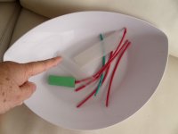
Interesting subject folks... at least to me.... heatschrink (retractable tubes) tubes are reducing diameter because exposed to light!... a friend asked me three days ago and i put them in the living room, nearby entrance door to give him the tubes.... and the place receive a lot of daylight, not direct sunshine, only difuse light reflected by apartment walls..and they are still reducing diameter.
We call these tubes, in Brazil, "espaguete" that comes from Italian pasta spaghetti.... has the tube shape... with a hole in the center.
In the reality these tubes looks more alike penne macarroni that has the tube shape.
regards,
Carlos
I cannot remember Terry...i am loosing memory.... it is deleting...i do think my brain is not working fine or it is too much filled with data ...i do not know...i need your help Terry, to help the guy is having ground problems.
I can remember that someone had...was the lifted ground not connected in one type of pcboard i think... the connection had to be made with wire...or disconected the lifted ground maybe....i do know people had ground loops..but i cannot remember where or when this happened...what thread... the guy had troubles or details alike that...if you can help, a this is something belongs to your soul, them please Terry, give us a helping hand.
Juan was in a break ..... that period of time he was in passion by tubes and i think he was not reading solid state threads...he may not know what happened.
Interesting subject folks... at least to me.... heatschrink (retractable tubes) tubes are reducing diameter because exposed to light!... a friend asked me three days ago and i put them in the living room, nearby entrance door to give him the tubes.... and the place receive a lot of daylight, not direct sunshine, only difuse light reflected by apartment walls..and they are still reducing diameter.
We call these tubes, in Brazil, "espaguete" that comes from Italian pasta spaghetti.... has the tube shape... with a hole in the center.
In the reality these tubes looks more alike penne macarroni that has the tube shape.
regards,
Carlos
Attachments


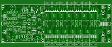
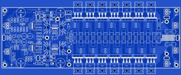
Today I was able to add an extra pair of power transistors, the only thing I might have to change is the GND connection I guess I add too manyany way I just want it to show you guys
Juan
Beautiful work Juan.
IMHO, the drivers MJE15030/31 would have a bad time driving 7 pairs of outputs. shift them on the main heatsinks.
Regards,
Aniket
Beautiful work Juan.
IMHO, the drivers MJE15030/31 would have a bad time driving 7 pairs of outputs. shift them on the main heatsinks.
Regards,
Aniket
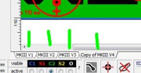
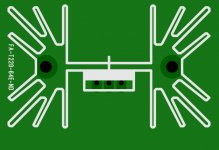
I might do that
at least what I do is clone the board to the same file if I made a mistake I can go back always, the heat sink I already made the macros for this part number FA-T220-64E-ND Digi KeyRegards
Juan
Attachments
Last edited:
Very good Juan
regards,
Carlos
thank you man
I will check this carefully no rush Regards
Juan
Hey Carlos sorry that I'm asking you old questions since I add an extra pair for Dx Blame MKIII I notice by curiosity that when I increase the power supply to +90V - 0 - -90V the THD goes down but if I use 64V as you recommended the THD goes up ? isn't that weird or not ?
Regards
Juan
Regards
Juan
Attachments
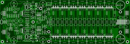
Today I made another copy of the layout with TIP35C/36C to see how much space is available and looks pretty good I think , today I will continue to see if there is any errata somewhere yep, is always something hidden jejejejejeje
Regards
Juan
, today I will continue to see if there is any errata somewhere yep, is always something hidden jejejejejeje Regards
Juan
Attachments
Great work Juan,
If Carlos permits, one more thing could be upgraded, i.e to convert it to a TEF output stage using one set of outputs as the drivers. although the drivers(MJE15030/31) could drive 7 pairs of high beta devices but the VAS would be heavily loaded driving a low impedance load.
Anyhow, your PCB design looks beautiful
Regards,
Aniket
Hey I only making the layout using same schematic that dear Carlos did same way,
I'm not trying to change it I'm only putting new "clothes Armor " to it to have a bit more juice the schematic remains the same I just add only one more extra pair that is it my friends, but seriously I'm fallowing Carlos schematic same way
Regards
Juan
I'm not trying to change it I'm only putting new "clothes Armor " to it to have a bit more juice
the schematic remains the same I just add only one more extra pair that is it my friends, but seriously I'm fallowing Carlos schematic same way Regards
Juan
Attachments

Looking good Juan,
One suggestion, maybe add some extra holes for the emitter resistors to give some choices.
Now that you mention I was thinking about that the other day I forgot thank you
Regards
Juan
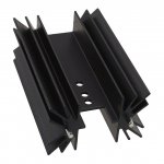
If you are going to drive 7 pairs of outputs, you should use bigger drivers - NJW0302/3281 or 2sa1943/2sc5200 would be ideal.
You could also consider adding pre-drivers but Carlos would not approve of that I'm sure :-D
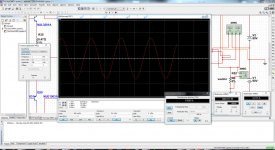
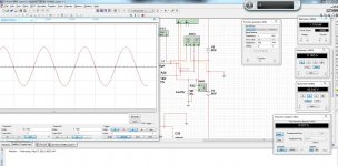
uhmm? well I have seen heat sink design for those type of transistors, I might see if I can place the drivers just a the power transistors on the same large heat sink or separate, I was simulation with multisim 13 and wow I understand that to have those result in real time I need a really large toroid transformers and lot of caps but this is great anyway according to the simulator at 2 ohms load it can give about 1178KW but for that to happen will need lot of current about 11A I'm only curious and also the THD stay really low too 0.007% ok dear Ranchu I will see what I can do with those larger transistors as drivers
Regards
Juan
Attachments
It is easy to increase current into drivers....the resistor
in between the emitters...just reduce it and you gonna have more current.
Current is enougth, not needed to increase...current is driving even 2 ohms loads.
Yes, i do not approve modifications into something that is working fine.
Also i do think we should not mess with diagrams accepted by several folks, and built by several folks..it is disrespect.... after they buy the idea and assemble you start to change the whole thing.
If people want to apply their own ideas, i do think they should buy the whole package... and not produce interferences in something others have worked hard.
To develop an amplifier we work as a horse ... or workhorse....we build, we make our mistakes and we burn parts.... we make prototypes .. we test them...we torture and we burn parts spending our own money and stock of parts to the advantage for the community that will receive the amplifier for free, and tested, and tortured and simulated.
We have to make layout, and this takes a lot of time (this one was easy as Alex mm can make it in a flip or his eyes...very fast Alex)
We have to advertise, we have to give follow up...we have to spend our money to produce pcboards for testing... we have to spend our money after that to order a lot of pcboards and we never know if people will order...if not we have to take the risk and to eat pcboards with ketchup.
We have to open a thread in the group buy...and to receive orders, and we have to take not of the adress of the one order.... we have to receive the payment for the pcboards and to buy envelopes, to write names on it and we cannot make any mistake..we have to ship them and if not return we are responsible to sent one more set of pcboards...a lot of responsability and work to us.
Then come someone and Andrewtize (the name i use together my friends)..just a name, that means we work and someone put the finger..say this is no good...make this way..change this and that....and we worked as a hell and the guy appear as the fried potatoes king that could make even better...this is unfair...the guy had not the onus.....but want the bonus...want to appear as clever, as wise and you working as an animal...i cannot agree and i react immediately against such kind of thing.
I do think people, if want to show themselves, or believe has courage and skills to make something to the community, then should take to himself all the responsability and all the work and expenses this produces to his pocket, mind and health and not to mess with other guys design/work and effort.
Several guys tried...i always react against...we see Ostripper tried...now he made his own...based into the same Blameless style amplifier..others tried.... we have Bigun...we have TGM in the place of Rodd Elliot amplifier..and so on....this is fair...they worked..they developed...they made their own in the place to be buzzing around trying to put the finger and to mess with other guy's work.
Not accepted any modification...the one wants to show and prove they are good..then go to work and make his own.
This way..for the development of our forum and community, we gonna have a lot of amplifiers... a lot of ideas...then people will have several pcboards available..several schematics and several guys giving follow up and helping builder to etch themselves (DIY is this way) and assemble themselves.
I not want tripple darlington in my amplifiers....for sure i know this feature exist since i was a kid.... or more than 50 years ago i already knew that.... for sure there's a reason i do not use..... and the reason is stability..no way for me to use tripple darlington because i want to keep my hairs on my head and not to be upset with people complaining about loss of power transistors and some buggers finding strange things in the waveform.
Also i do not use double differential and i have my reasons for that.....also i use this kind of schematic because it is the best i could ever find in my 53 years building and liistening audio amplifiers.
So....no tripple darlington to the Dx Blame MKIII....but of course, people that has their boards, if they want they can try...but will not be with my blessings and support and lose the warranty and help or follow up.
In other words...the one wants to be "then man!"...then work hard to be "the man" and do not try ever, to modify stuff in other guys units...make yours...open your thread and work hard to deserve fame and the joy to be serving the community and also feeding your soul and pride having the result of your work playing in a lot of friend's home..... but accept the onus and not try to have a free bonus without work messing up with other guys work...andrewtize is the name i use...and this have a meaning to me and to my partners.
I understand your point Ranchu...but suggestion not accepted...thanks a lot by your good will to help us.
Juan is not authorized to make any modifications...he knows that and for sure will not feed this kind of conversation.
Imagine if we do that.... all builders will be betrayed.
They will think....well...i have bougth expensive enclosure...i have bough expensive capacitors.... and parts... i have ordered pcboards..worked several weekends....burned my fingers...and have made an amplifier that was tested..and now Carlos come with that stuff that need one more stage..and my pcboard gonna be lost...the good amplifier is no good anymore?.... this will not happen...i will not accept this..they will not be betrayed.
Uncle Charlie will always fight against modifications.... i protect my amplifiers the same way i protect my sons....always ready to a good fight... even knowing the guy has the good intentions...that wants to help...but does not help as i have explained and i will always react.
regards,
Carlos
Attachments

Last edited:
Carlos do not worried this is my personal project not intended to change the original Dx Blame MKIII the schematic is the same so I notice you wrote that long paragraphs that means that it does bother you so I will not show the project anymore here and keep it to myself is that what you want then I will close this subject today and not show it anymore this new layout and keep it to myself is that what you want? I will respect your answerer like a gentlemen no problem dear friend .
Best Regards
Juan
Best Regards
Juan
Attachments

- Status
- Not open for further replies.
- Home
- Amplifiers
- Solid State
- Dx Blame MKIII-Hx - Builder's thread