KB262 Diode
You can order then from here:
Search results for kb262
They are out of stock but shows there on order, lead time <30 days. You can also use RVDKB262D as a sub, that's a Panasonic part. I only have 4 in stock at this time, I also need to order another 12 to keep on hand. Other than that you have also:
https://www.encompassparts.com/webwiz/wwiz.asp?wwizmstr=WEB.SEE&partnumber=521885
You may be waiting forever if you order from them, they sometimes take months to get the part and ship it out. They have a habbit of selling parts they do not have and then scramble to fill the order only after you call over and over again. Even then you might recive another sub like NTE or ECG that you do not want. I would stick to MCM for that part unless some else has a sugestion.
Resurrecting this thread, as I think I've found the answer! Please give feedback!
Scant information is available on these KB362 and KB262 diodes. The service manual lists them as "Varactor diodes", but I think this is a mistake. I believe they are actually "Stabistor diodes". They are avalanche diodes designed for highly stable forward voltage versus current. They come in packages containing 1-4 P-N junctions in series, and so the parts numbers tend to reflect this. KB262 has two diodes, and KB362 has three.
I found an scan of an old parts catalogue on the internet somewhere with the KB262 and KB263 listed. I could not find an actual datasheet, but various sources suggested crossing with Phillips BZV86, and this is what led me to believe they are stabistors.
KB262 - Si-St Vf 1.4V (@10ma?)
KB362 - Si-St Vf 2.1V
This makes sense. If the 262 has two diodes with a Vf of 0.7V, then the 362 should have three diodes, and be 2.1V, which it is.
I did some measurements of actual diodes from a GFA-565, and the Vf versus If jibes well with what I've found on the datasheets.
So, I found a few parts that should work, only one of which is still being made. Their Vf vs. If seems pretty close.
1N4156 and 1n4157
Digitron MPD200 and MPD300
Phillips BZV86-1V4 and BZV86-2V0
All the above are hard or impossible to find.
BUT! Central Semiconductor makes surface mount stabistors!
CMXSTB200 = KB262
CMXSTB300 = KB362
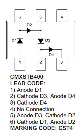
Mouser has the 200 (two diodes) and 400 packages in stock, but not the 300. However, one can simply buy the four-diode package and not use one of them. Here's the pinout...
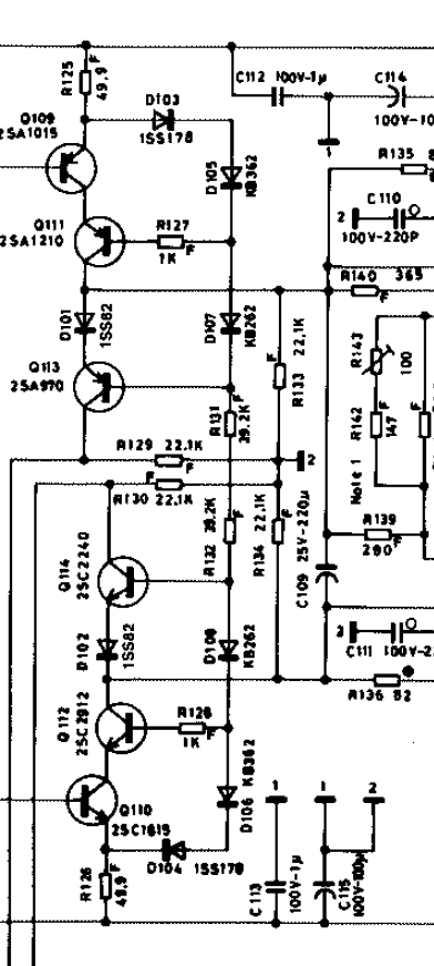
And here's where they go in the circuit.
Anyone see any issues with this?
Scant information is available on these KB362 and KB262 diodes. The service manual lists them as "Varactor diodes", but I think this is a mistake. I believe they are actually "Stabistor diodes". They are avalanche diodes designed for highly stable forward voltage versus current. They come in packages containing 1-4 P-N junctions in series, and so the parts numbers tend to reflect this. KB262 has two diodes, and KB362 has three.
I found an scan of an old parts catalogue on the internet somewhere with the KB262 and KB263 listed. I could not find an actual datasheet, but various sources suggested crossing with Phillips BZV86, and this is what led me to believe they are stabistors.
KB262 - Si-St Vf 1.4V (@10ma?)
KB362 - Si-St Vf 2.1V
This makes sense. If the 262 has two diodes with a Vf of 0.7V, then the 362 should have three diodes, and be 2.1V, which it is.
I did some measurements of actual diodes from a GFA-565, and the Vf versus If jibes well with what I've found on the datasheets.
So, I found a few parts that should work, only one of which is still being made. Their Vf vs. If seems pretty close.
1N4156 and 1n4157
Digitron MPD200 and MPD300
Phillips BZV86-1V4 and BZV86-2V0
All the above are hard or impossible to find.
BUT! Central Semiconductor makes surface mount stabistors!
CMXSTB200 = KB262
CMXSTB300 = KB362
Mouser has the 200 (two diodes) and 400 packages in stock, but not the 300. However, one can simply buy the four-diode package and not use one of them. Here's the pinout...
And here's where they go in the circuit.
Anyone see any issues with this?
Last edited:
OK, I am more and more confident this is the answer. I received the CMXSTB200 and 300 diodes, and the measurements match the original diodes closely.
This latest pair of 565's I'm working on don't have the usual KB262 and KB362 in the small epoxy-blob package. Instead, there are black and pink diodes in cylindrical cases, which I assume are 1N4156 and 1n4157 or BZV86.
Mystery Stabistor #1 (KB262 position, two-junction diode)
0.1ma = 1.05v
1ma = 1.18
3ma = 1.25
5ma = 1.29
10ma = 1.35
Mystery Stabistor #2 (KB362 position, three-junction diode)
0.1ma = 1.55v
1ma = 1.74
3ma = 1.84
5ma = 1.9
10ma = 2.0
CMXSTB200
0.1ma = 1.0v
1ma = 1.2
3ma = 1.32
5ma = 1.37
10ma = 1.44
CMXSTB300 (Actually STB400 with one diode unused)
0.1ma = 1.5v
1ma = 1.8
3ma = 1.98
5ma = 2.05
10ma = 2.17
Here's how I converted the surface-mount diodes to through-hole...
I soldered thin leads to them
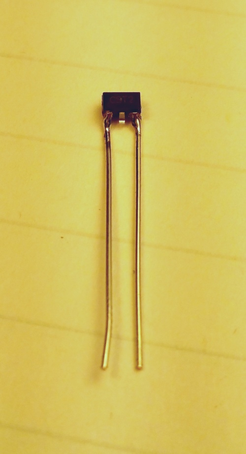
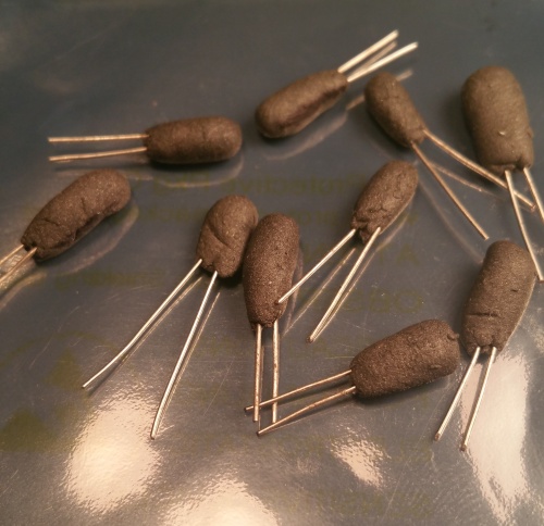
Then a blob of JB Weld putty epoxy.
I'll be trying these diodes in an amp soon, and I'll update this thread, as well as the other thread where this is being discussed...
http://www.diyaudio.com/forums/solid-state/286742-yet-another-adcom-gfa-565-thread-32.html
This latest pair of 565's I'm working on don't have the usual KB262 and KB362 in the small epoxy-blob package. Instead, there are black and pink diodes in cylindrical cases, which I assume are 1N4156 and 1n4157 or BZV86.
Mystery Stabistor #1 (KB262 position, two-junction diode)
0.1ma = 1.05v
1ma = 1.18
3ma = 1.25
5ma = 1.29
10ma = 1.35
Mystery Stabistor #2 (KB362 position, three-junction diode)
0.1ma = 1.55v
1ma = 1.74
3ma = 1.84
5ma = 1.9
10ma = 2.0
CMXSTB200
0.1ma = 1.0v
1ma = 1.2
3ma = 1.32
5ma = 1.37
10ma = 1.44
CMXSTB300 (Actually STB400 with one diode unused)
0.1ma = 1.5v
1ma = 1.8
3ma = 1.98
5ma = 2.05
10ma = 2.17
Here's how I converted the surface-mount diodes to through-hole...
I soldered thin leads to them
Then a blob of JB Weld putty epoxy.
I'll be trying these diodes in an amp soon, and I'll update this thread, as well as the other thread where this is being discussed...
http://www.diyaudio.com/forums/solid-state/286742-yet-another-adcom-gfa-565-thread-32.html
Looking at the diode stack in the schematic, I see that the total voltage drop is about 80 volts (85 volt rail, and about 4-5 volts in diode drops). The resistance in that stack is about 39.25K ohms, so the total current is about 2 mA, not 10.
That puts the drops for your Stabistors at about 1.2 v and 1.8 v, but your parts seem to match over the range, so this looks like a good solution.
I always wondered about the "Varistor" aspect. A varistor has a dual I-V curve, so it acts like two parallel diodes with opposite polarity, that is it has a negative I-V part and a positive one. In this circuit all of the current is forward, so a varistor would be useless. In addition, the match between the diodes in the stack (top matched with bottom) is important for maintaining the DC balance bias, which translates to DC offset.
Nice work! For a more truly representational equivalent, I think you should paint the epoxy covers properly though (half black and half orange for one, and half black half cream for the other!) :-D
Scott
> "Varactor diodes", but I think this is a mistake.
Agree. (Though I think "varactor" would be an alternate name for variable capacitance diode for radio tuning.)
> I believe they are actually "Stabistor diodes". They are avalanche diodes designed for highly stable forward voltage versus current.
"Avalanche" would be several volts or more, reverse-biased. "Zeners" above a few volts are really avalanche diodes, and as-stated sold as stable several-volt references.
Here they are used in *forward* conduction giving about 0.6V per junction.
> packages containing 1-4 P-N junctions in series, and so the parts numbers tend to reflect this. KB262 has two diodes, and KB362 has three.
Yes. Many semi shops had a large range of "bias diodes". They could use-up the "reject" junctions that had mild leakage or didn't have good PIV performance. They could stack several in one package. For a few bucks they would tight-select voltages and print your part number.
Looking at the circuit-snip, here they are not even precision references used, say, to set idle current. They are just blocking-up one transistor above the next, with just enough voltage to let the transistor be "active".
Myself I could see wads of 1N914/4148 or even 1N4007 diodes stacked to the correct number of junctions. I don't even think JB thermal bonding matters. The CMXSTB part is a sweet find.
I do think it may matter that, say, D101 is similar to D107. So it may be wise to replace all with "the same thing".
Wonder why they are blowing? There's no stress (<1mW/diode) normally. Can there be big reverse voltage kicks? Can't tell from the snip, and don't really want to see the full monty-- that plan is too complicated for my brain. Or OTOH were these "bias diode packs" really and truly assembled from "reject junctions", which failed normal tests because the dopant or sealing was poor and they fail over time?
Last edited:
> "Varactor diodes", but I think this is a mistake.
Agree. (Though I think "varactor" would be an alternate name for variable capacitance diode for radio tuning.)
My bad.. My RF background is showing through. They are listed as VARISTORS..But I think they are really sable forward voltage references.
> Myself I could see wads of 1N914/4148 or even 1N4007 diodes stacked to the correct number of junctions. I don't even think JB thermal bonding matters. The CMXSTB part is a sweet find.
I do think it may matter that, say, D101 is similar to D107. So it may be wise to replace all with "the same thing".
Wonder why they are blowing? There's no stress (<1mW/diode) normally. Can there be big reverse voltage kicks? Can't tell from the snip, and don't really want to see the full monty-- that plan is too complicated for my brain. Or OTOH were these "bias diode packs" really and truly assembled from "reject junctions", which failed normal tests because the dopant or sealing was poor and they fail over time?
This was where this started. I had one amp that had several 1N914 diodes in series...The originals in many amps are unmarked little blobs, Black on one end and white or orange on the other.
A few of mine have been blown, but not often. I think the issue probably arises when/if one of the transistors fails shorted, or if a tech accidentally shorts one to ground. This might also happen with an electrolyte pickled board (from the leaking capacitors), allowing some stray current path. Any of this could put a big jolt of current through them, and they are very small, so presumably not made to tolerate that. Under normal operation they are barely pushing 2 mA.
It is also possible that, being custom, they were not well potted, and ended up with some internal oxidation.
I'd say less than about 1 in 10 I have seen have been bad...BUT, when they ARE bad, then they are hard to replace.
S
Gah, yes! Service manual says varistors, not varactors. Anyways, they're stabistors.
I only did the jb-weld potting so the leads don't get stressed. One could probably do without.
I haven't seen any of these diodes blown out before, but this set of 565's came to me with the stabistor diodes installed in the wrong spots! And they weren't the usual KB262 and 362, so I wanted to find out what's really supposed to be there.
PRR, thanks for the correction. Stabistors are indeed tunnel diodes. I went down the rabbit hole and discovered this 1964 GE Transistor manual, chock-full of nerdy stuff about stabistors, snap diodes and the like. I thought this was an interesting passage...
Would a stabistor be a better performing reference for a transistor current source that feeds a long-tail-pair, versus the usual string of two 4148's?
I only did the jb-weld potting so the leads don't get stressed. One could probably do without.
I haven't seen any of these diodes blown out before, but this set of 565's came to me with the stabistor diodes installed in the wrong spots! And they weren't the usual KB262 and 362, so I wanted to find out what's really supposed to be there.
PRR, thanks for the correction. Stabistors are indeed tunnel diodes. I went down the rabbit hole and discovered this 1964 GE Transistor manual, chock-full of nerdy stuff about stabistors, snap diodes and the like. I thought this was an interesting passage...
When the multi-pellet stabistor is used as a voltage regulator, the temperature coefficient of the stabistor will be larger than a breakdown diode of comparable voltage. However, this is offset by the stabistor's tighter initial tolerance, lower dynamic impedance, and absence of noise at low currents.
Would a stabistor be a better performing reference for a transistor current source that feeds a long-tail-pair, versus the usual string of two 4148's?
Would a stabistor be a better performing reference for a transistor current source that feeds a long-tail-pair, versus the usual string of two 4148's?
I would think so. The voltage source for the constant current source sets the current by setting the voltage across the emitter resistor in the CCS. The voltage across the resistor is Vd- Vbe, so the current is then
(Ie+Ib)=(Vs-Vbe)/Re. Where Hfe is the beta of the transistor.
Ie=(Hfe)Ib, so...
Ie=(1+1/Hfe)(Vs-Vbe)/Re=[Hfe/(1+Hfe)][(Vs-Vbe)/Re]
Notice that since Hfe appears in the numerator and the denominator of the first term, as long as Hfe is somewhat large, changes in Hfe over temperature, current or time are swamped out. For example if Hfe=200, then a 10% change in Hfe will cause the first term to go from 200/201=0.995025 to 210/211=0.99526, a change of only 0.03%...
If the resistor is noisy (which is easy to avoid using a stable film resistor), or if the voltage across the diode changes (which can be avoided by using a stabistor, or a low noise zener, then the current is both stable and low noise .
S
What voltage drop are you getting on D103 and D104? The data sheet for the 1SS178 diode lists Vf at 1 volt, but that's at 100 mA. The diode stake is operating at 2 mmA, so the VF is presumably lower. It appears that the diode drops on the Stabistors are about 0.6 volts each
I am wondering if it might work to use two CMX 300 devices and just tap out of the stack at the appropriate places. to get the right voltage drops. That not only saves parts but concentrates the diodes in the same physical space, thereby assuring that they are all at the same temp.
Use pins 1 and 6 of a CMX 400 for D103, Pins 6 and 3 for D105, and pins 1 and 3 of a CMX 200 for D107...
Also, on my latest amp, the one with the new board, I noticed the waveform was somewhat distorted at higher signal levels. I traced this to the clipping circuit based on D101 and Q113 (and the negative side counterparts). I had used a 1SS82 equivalent for that diode (D101), but apparently it is not equivalent enough! Clipping the lead on the diode cleaned up the waveform instantly.. so I suppose the IV knee on the equivalent is both too low (Vf) and perhaps too soft. Have you had any experience like this?
I almost wonder if a zener might be better there...I am not too concerned about hard limiting, as I do not ever play these ay anything like full volume! I wonder if simply eliminating the clipping indicator and limiter altogether might improve the performance...
Scott
Last edited:
Ah, I didn't write it down, and haven't got a 565 in the house at the moment, sorry.
Yes, I was wondering what the logic was behind using the 1ss178 in series with the stabistors. ...seems to defeat the purpose of a stabistor, as the whole stack will fluctuate along with that diode. Maybe it doesn't matter as long as they all do it?
Could it be that it's there to limit damage in case of a failure? For it's reverse voltage?
I've been using Vishay 4148 and haven't had any distortion issues.
I found two issues with the rail voltage/output signal level issue. First, I had jury rigged the power feeds to the board so I could move it out into a panavise on my bench. The connections were just twisted and taped. I soldered those and the rail droop went away.
I also changed the 1SS178 diodes, and that solved the overall output level issue. I had changed these out for a higher Vf diode when troubleshooting the board, and forgot to swap them back. The higher Vf meant that Q110 and Q109 were saturating at a lower input signal level. As soon as I changed them the output swing went to nearly 80 volts!
This is much higher than usual, and it is because I have D101 and D102 out of the circuit... So there is no active soft clipping in place. I'll try putting them back now that the board is rock solid.
I am also anticipating measuring the trim pots in R144/145. Once the amp was stable, I set the currents on Q111/112 using these pots. They are interdependent because the diode stack doesn't have a hard ground between the positive and negative ends (i.e. between R131/132). So you have to go back and forth numerous times. Adjust the drop across R126 and then R126 (to 0.8 volts for 16 mA quiescent current.. which seems to be the proper bias point based on my analysis). If you set one to 0.8 volts then the other will be at, say 0.7, so you adjust that one to 0.8 and then the first one will be at 0.85 or so.. So you go back and forth Increasing one and decreasing the other until both are at 0.8 volts. I'll measure the pots today and see how far they are from each other, and from the original resistor specs (499 ohms)...Probably just put the 499 ohm devices back in...The Vishay trimmers are nice for troubleshooting though!
The Vishay 4148 device looks to be exactly the same specs and the NTE 519 which was listed as the 1SS178 equivalent.
The good news is that the replacement board layout seems to work fine (at least when it doesn't have solder splatters on the traces!)
BTW, Mouser has 12K CMXSTB-300 devices available in 10 days.. We'll have to wait and see if they back down on their 3000 minimum quantity...I don't think there are enough Adcom 565s out there to justify that volume buy!!.
I think I'll work up some rabbit turd diodes like you did and put them into this amp, and button it up.
My next plan is to replace the boards in all of the 565s I have (using the new CMX SMT layout), pick the best three and probably sell the others. I'll provide the original board with each amp in case the new owners want to spend their time chasing electrolyte issues... :-D
Last edited:
- Status
- This old topic is closed. If you want to reopen this topic, contact a moderator using the "Report Post" button.
- Home
- Amplifiers
- Solid State
- Adcom GFA 565 Diodes