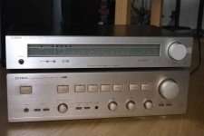
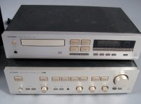
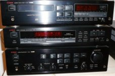
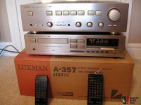
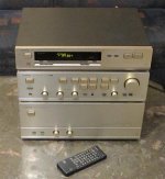
For this Luxman hifi system I need a new MCU for each component.
The type No are follow:
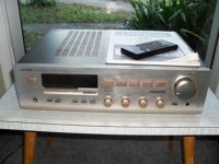
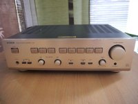
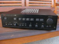
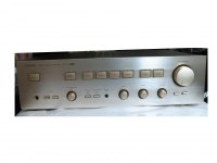
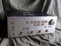
1) Integrated Amplifier "A-373": TMP47C860N-G091
(TMP-47C860N-G091) Toshiba
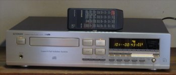
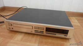
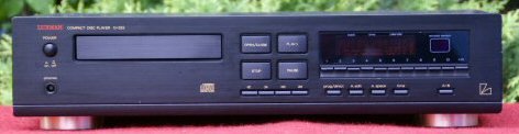
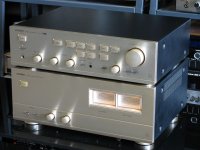
2) Compact disc player "D-375": HD404729877S-35096WO3 (HD-404729877S-35096WO3) Hitachi
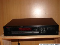
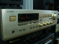
3) Stereo FM Tuner "T-353": TMP47C862AN-P527
(TMP47C862AN-P527) Toshiba
All parts are no longer available. Thus I am looking for other possibilities.
First possibility is to find out other models and brands with the same MCU's and same firmware.
Perhaps one of you know any models (most important is the amplifier).
Second possibility is to buy universal MCU's without firmware for own programming and additional the genuine Luxman firmware.
Who know appropriate delivery sources and suppliers for this?
BTW - the last is a general problem by much more other old audio components and therefore I think, there are some special company for offer this.
Thank you very much for your advices.
The type No are follow:
1) Integrated Amplifier "A-373": TMP47C860N-G091
(TMP-47C860N-G091) Toshiba
2) Compact disc player "D-375": HD404729877S-35096WO3 (HD-404729877S-35096WO3) Hitachi
3) Stereo FM Tuner "T-353": TMP47C862AN-P527
(TMP47C862AN-P527) Toshiba
All parts are no longer available. Thus I am looking for other possibilities.
First possibility is to find out other models and brands with the same MCU's and same firmware.
Perhaps one of you know any models (most important is the amplifier).
Second possibility is to buy universal MCU's without firmware for own programming and additional the genuine Luxman firmware.
Who know appropriate delivery sources and suppliers for this?
BTW - the last is a general problem by much more other old audio components and therefore I think, there are some special company for offer this.
Thank you very much for your advices.
Attachments
Last edited:
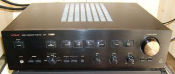
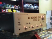
Luxman R-341 has same MCU as A-373
Hi tiefbassuebertr,
I guess this may be of some help to you. Luxman R-341 (possibly R-351) receiver has the same MCU - TMP47C860N, but I am not sure of the firmware in it. Usually these receivers go for cheap on Ebay (at least in US), it can be your source for this MCU. Otherwise, IMHO, it is too much hassle to make it work with general MCU. I do recall someone replaced a broken MCU in his Telefunken receiver (80s or 90s Japanese design) with some PIC controller. Need to search the internet.
Best of Luck,
Routhu
Thank you for the advice of your keywords in this matter - I think you mean this URL:
http://john.ccac.rwth-aachen.de:8000/misc/rt200rep/
Good paper in case of such problems in general.
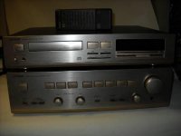
Concerning the mentioned Luxman devices I will also check your mentioned receiver models so as the Amp A371.
I would like to know all exist models of the Luxman series R-T-D-A 3xx.
By the Luxman heritage site this series isn't completly mentioned.
http://john.ccac.rwth-aachen.de:8000/misc/rt200rep/
Good paper in case of such problems in general.
Concerning the mentioned Luxman devices I will also check your mentioned receiver models so as the Amp A371.
I would like to know all exist models of the Luxman series R-T-D-A 3xx.
By the Luxman heritage site this series isn't completly mentioned.
Attachments

Last edited:
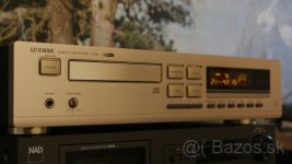
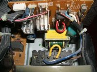
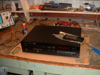
The repair work was finished by the models A373 and T353 (I have found devices of the same models but in optical worse condition).
I replaced the internal stuff against each other.
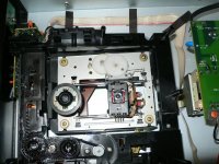
For the D375 I have purchase a MCU as replacement part.
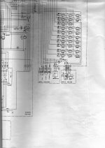
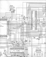
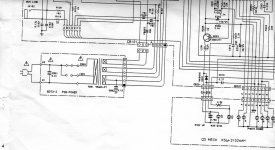
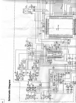
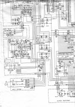
Before I perform the replacing, I need the schematic of this part.
Voltage are all correct after replace the regulators, but I don't understand, how the st-by control unit works.
Who can post the schematic of the D375 ?
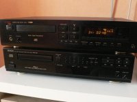
Here are more models in the outline of D375, but completly other internal chip-sets
I replaced the internal stuff against each other.
For the D375 I have purchase a MCU as replacement part.
Before I perform the replacing, I need the schematic of this part.
Voltage are all correct after replace the regulators, but I don't understand, how the st-by control unit works.
Who can post the schematic of the D375 ?
Here are more models in the outline of D375, but completly other internal chip-sets
Attachments
-
 Luxman D321 front.jpg18.6 KB · Views: 77
 -
 Luxman d322 black front.jpg15 KB · Views: 64
 -
 Luxman D322+A353 front.jpg157.5 KB · Views: 66
 -
 Luxman D357 front.jpg47.2 KB · Views: 70
 -
 Luxman D355 front.jpg23.5 KB · Views: 132
 -
 Luxman D351-A371.jpg21 KB · Views: 200
 -
 Luxman D357 HOPM3 mechanism.jpg81.1 KB · Views: 222
 -
 Luxman D373 front.jpg18.3 KB · Views: 109
 -
 Luxman D373 front-II.jpg31.3 KB · Views: 116
Last edited:
and various additional images of the integrated amps from this outline series:
Attachments
-
 luxman A353 black front high res.jpg729.3 KB · Views: 178
 -
 Luxman A357 - D375 front.jpg84.7 KB · Views: 164
 -
 luxman A377 front black.jpg30.7 KB · Views: 106
 -
 luxman A377 stby PCB.jpg59.9 KB · Views: 156
 -
 luxman A377 open top.jpg72.5 KB · Views: 247
 -
 luxman A377 front.jpg27.5 KB · Views: 103
 -
 luxman A383 front black.jpg37.6 KB · Views: 108
 -
 luxman A383 front.jpg123.8 KB · Views: 102
 -
 luxman A383 top open.jpg57.3 KB · Views: 142
 -
 Luxman A388 front.jpg85.2 KB · Views: 152
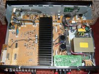
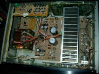
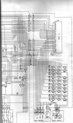
I wonder, why at pin 16 ("Power ON") from the replaced MCU isn't to observed any activity after pressing the "ON" botton.I have a like new D375, can I be of help?
Thus the cd player remains in the stand by mode. Display is death.
The voltages from the power supply are all resent in the right value. The PIN "OSC1" works - i. e. MCK is present.
How can I prove whether the new MCU is defective again, or whether the error is outside of the MCU ??
HD404729 datasheet and application note, data sheet, circuit, pdf, cross reference, pinout | Datasheet Archive
Attachments
Last edited:
Similar situation with R117s
I have similar situations with R117s, I have working remotes, original R117 remotes, but they do not work with the R117s I have. I can help explore this, but not until Sunday at earliest. I have an R117 in pieces on my workbench that takes up all my bench room until them. But I will look at the schematics and work the problem from a logical view. Silly question maybe, but how do you know the IR on the remote is firing the correct code?
I have similar situations with R117s, I have working remotes, original R117 remotes, but they do not work with the R117s I have. I can help explore this, but not until Sunday at earliest. I have an R117 in pieces on my workbench that takes up all my bench room until them. But I will look at the schematics and work the problem from a logical view. Silly question maybe, but how do you know the IR on the remote is firing the correct code?

I don't know this. I haven't check the behaviour with the associated remote control. I have check only by press the front buttons.I have similar situations with R117s, I have working remotes, original R117 remotes, but they do not work with the R117s I have. I can help explore this, but not until Sunday at earliest. I have an R117 in pieces on my workbench that takes up all my bench room until them. But I will look at the schematics and work the problem from a logical view. Silly question maybe, but how do you know the IR on the remote is firing the correct code?
I don't know this. I haven't check the behaviour with the associated remote control. I have check only by press the front buttons.
Oh, my misunderstanding, I thought your issue was with the remote not activating the unit. It would not hurt to try the remote as either one should turn it on. If neither one turns it on then it is downstream from the on circuit I would think. Maybe an Or-Gate IC in the signal path gone bad?
I have the unit open on the bench and am looking at the pieced together schematics to see what I can come up with. If you need to know of some voltage or state readings from a working unit let me know.
First test results
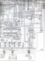
I had a moment to cut and tape together the schematics, some parts are not continuous/missing, and was able to follow your posts a bit better. I don't have much time each day to work on this during the weekdays, but I will do what I can. Below is what I have found to your question on Pin16.
At IC204, at the D202 junction which is the same as Pin16, the voltage with the unit plugged in and not powered up was -23.56v dc. With the unit powered up the voltage went to 4.65v dc and remained constant.
Not much help yet, but it is a start.
I played with the CD a little and a couple of things came to mind.
1. Unit power switch drives whether any of the other buttons are active and this could be your problem point. Check the operation of this and the downstream functions it activates.
2. The failure sounds like a single point failure. That would suggest power to the ICs, the above power switch observation, or maybe the clock to syncronize functioning is not working.
A friend tell me, that several models made after 1990 from Luxman OEM versions - i. e. only branded with the Luxman logo.
Maybe this is the reason for the not available service manual under model naming "A-373".
Maybe one of the member know brand and model name from the actually manufacturer.
Maybe this is the reason for the not available service manual under model naming "A-373".
Maybe one of the member know brand and model name from the actually manufacturer.
- Home
- Amplifiers
- Solid State
- Luxman A373 - D375 - T353 Integr. Amp - CD - FM-Tuner