Sorry about that,
Don't know what I was think, here goes with a fixed version
<pre>
+-----+-----+---+-{2k2}-+----+-------------+- +25V
| | | | | | |
| | | | | |T| |
| | | | | |H| D33A 1
_|_ __|__R | | | | R
2n2___ /Z\ D | | | 3 |
| | 9 | | 2 k E--C 2
| | A 8 | K 3 2SA634 S
+-----+ K | 2 | C----B D
| 2 | +----+-----B | 1
| | | | | E 8
GND | | C | | 8
+---(------B 2SC815 | |
| | E | |
2 | | | |
4 | | 1 |
0 | | K |
R | | | |
| | | | |
+---B E C-(-+ | | |
| 2SA539 | | | | |
| | | 5 | |
-{4k7}-+---+ | | 0--+-{200R}---+----+--
| | | | 0 | | |
1 | 2SC815 / | R 1 | |
0 +---B E C / | 0 | |
k | | | R | |
| | | | | | |
GND 2 | | GND | |
4 | | 1 |
0 | | K |
R | | | |
| | E | |
+----(-----B 2SA539 | |
| | C | |
| | | | E 2
| | +----+-----B | S
GND 8 | | | C----B A
| k | 2 3 2SC1096 6
+-----+ 2 | k k E--C 2
| | | | 2 3 | 7
_|_ __|__R | | | | |
2n2___ /Z\ D | | | |T| 1
| | 9 | | | |H| D33A R
| | A | | | | |
+-----+-----+----+-{2k2}+----+-------------+ -25V</pre>
As for the D-33A, Toshiba may have lost its thermister range when it sold Marcon to United Chemicon, none of the Toshiba or United Chemicon websites have any thermistors listed.
Regards
James
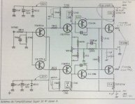
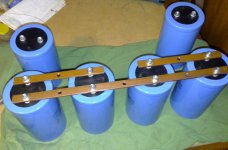
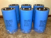
No, I don't use thermistors. I used the circuit shown here: http://www.tcaas.btinternet.co.uk/hiraga3.htm The only change I've made is the value of the bias resistors so that I get 2A quiescent current. I also used a computer to match the small signal transistors - the system measures them and then the software determines the closest match. And I'm not using all that capacitance; I use 4x10,000 uF BCH caps per rail on each monoblock. If you do the PCB tracing and wiring correctly, you'll get no hum at all.
J.Guilherme
J.Guilherme
Selection of components
Hi grataku,
Looks interesting with the 20W amplifier. I built some versions of the "Le Monstre", which in my opinion sounded "good" and belied its power of 8 watts. I have also built the "Kaneda" pre-amplifier and "Le Pre-Pre" moving coil cartridge amplifier.
One of my experiences with L'Audiophile circuitry is that their sound can be quite sensitive to the choice of components. In my memory the choice of components was one of the areas where L'Audiophile put quite some effort, be that in terms of transistors, resistors, capacitors or .... ? Not to say that their choice of components will work well in your system - just mention it.
I have built amplifier circuitries of a complexity similar to "Le Monstre" on balsa -wood boards, which in my opinion makes the sound softer, more open and effortless. Maybe due to much less dielectric absorption ? These amplifiers were wide-band (MHz cut-off frequency), single-ended designs and sound-wise and stability-wise they profited from placing small ferrite beads (like those used e.g. on computer mainboards) on the transistor legs. I used these beads both on the small-signal transistors and output transistors.
Anyway, the best for your efforts,
Jesper
balanced input for Hiraga ?
older thread - new question:
I'm not that strong in circuit design, but if I'm right it shouldn't be to difficult to implement a balanced input @ Hiraga ... anybody an idea about dimensioning & best strategy (esp. 'point of input' & input impedance)
thanks
Tilman
older thread - new question:
I'm not that strong in circuit design, but if I'm right it shouldn't be to difficult to implement a balanced input @ Hiraga ... anybody an idea about dimensioning & best strategy (esp. 'point of input' & input impedance)
thanks
Tilman
Nordic said:I have 7 page pdf may 07 silicon chip mag article...
Little short on bandwith, willing to share with someone who will share around again...
shoot me with this file
to >sasica5@gmail.com<
and I'll see what I can do .......
Nordic said:Sorry I seemed to have confused it with another class a... send you the files anyway..
just downloading them ;
I'll check.........

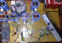
Hiraga class A test setup on the scope
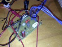
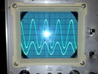
And here is the amp running on the scope.
larger waveform is 10V/div (approx 19Vrms)
load is 8 Ohm resistive
Frequency is 20kHz.
approx 45 Wrms 8 Ohm resistive. Class A.
Those poor little output transistors.
-Dan
And here is the amp running on the scope.
larger waveform is 10V/div (approx 19Vrms)
load is 8 Ohm resistive
Frequency is 20kHz.
approx 45 Wrms 8 Ohm resistive. Class A.
Those poor little output transistors.
-Dan
Attachments
Re: Hiraga class A test setup on the scope
Yes, at 80 watts each, they are cooking.
danieljw said:Those poor little output transistors.
Yes, at 80 watts each, they are cooking.
- Status
- This old topic is closed. If you want to reopen this topic, contact a moderator using the "Report Post" button.
- Home
- Amplifiers
- Solid State
- Hiraga 20W class A