.jpg")
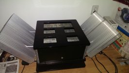
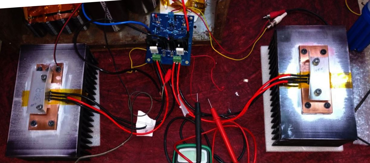
wanted to check the PSU - excuse me for the wiring mess. voltage without load is 28.8 volts! this is with 20-0-20 secondary [400VA] trafo. if i connect automotive lights [2 bulbs of 12V in series - not sure of the wattage - they are the small signal indicators] output voltage drops by around 1 volt. my amp board needs 24 volts per rail - hopefully it'll work fine.
i kept the circuit powered on for few minutes. to begin with there were no fireworks
 . i didn't see anything heating up either. i thought the resistors would heat up but they were very slightly warm to touch [wire wound, ceramic type, 0.5 Ohms, 25 W].
 after powering down, if i connect the contraption of bulbs, they drain out the juice within few seconds [around 5-6 secs per rail].
20-0-20VAC will give you 24VDC under Class A load like the Hiraga Class A. That will be perfect to you for your requirements.
I m not sure the 0.5R resistor can handle the heat under the mentioned load even do it is 25W type. I usually ad a PC of heatsink to that resistor (not the main heatsink)
Greetings
I m not sure the 0.5R resistor can handle the heat under the mentioned load even do it is 25W type. I usually ad a PC of heatsink to that resistor (not the main heatsink)
Greetings
what type of resistor do you suggest gabobela? i'm looking for metal jacket power resistors but unable to source them locally!
also, i'm planning to use bleeder resistor of 6K Ohms,25 Watts [preferably metal jacket type] between the two rails [single resistor]. will that work? also do I need a bleeder once the amp is ready? won't the speaker load will use up all the residue power when i turn off the power to the amp?
also, i'm planning to use bleeder resistor of 6K Ohms,25 Watts [preferably metal jacket type] between the two rails [single resistor]. will that work? also do I need a bleeder once the amp is ready? won't the speaker load will use up all the residue power when i turn off the power to the amp?
I meant when you build your PS like C-R-C the 25W resistor may get to warm. You can use 2x 0.5R parallel. If you bias your amp at least 1.2A or so the two PC 25W (1x 50W 0.25R) resistor will do the job. With the 0.5R resistor you will burn up lot of power, higher the bias more power burn, no need for that much. You can use more caps and only one resistor per rail. Hiraga need high capacitance for good filtering.
For bleeder I think 1W more than enough if you pick the right value.
I think 6K or 10K will be enough I never used one.
Greetings
For bleeder I think 1W more than enough if you pick the right value.
I think 6K or 10K will be enough I never used one.
Greetings
Hello bhp,
The 28v per rail is as expected. After you hook up only a channel you will end up with aprox 26.7~27v if you bias your amp as Dan and i did at 1.65A.
I used in the past 1r/20w wich fried my fingers each time i wanted to check them, and now i'm using 0.22r/30w wich is barelly warm (about 6degrees celsius above room temp) so i put these resistors near the caps. I think your 0.5r/25w will get warmer, but if you paralel two of them the situation gets cooler than my case.
I didnt use a bleeder because the amps drains aprox 1F in max 5 seconds at the worst case, when nothing is conected at the input. But for tests and listening trials and swapping components i used a 220r/ 8w wirewound resistor for fast discharge in aprox 10 secs.
Cheers
Sergiu
thanks gaborbela and sergiu,
regarding resistor, i've another pair of resistors which are 0.25 Ohms/ 30W , probably will replace the existing ones.
and yes, even i'm not planning to use bleeder in the final version. during construction, i've a pair of bulbs which help me drain out the caps.
i'll be using little more than 0.5 Farad caps per channel [14X10,000uF+4X100,000uF] .
i'm yet to put together the amp board. hopefully will do so in a week. been working on heat sink prep as well. now i need to hunt for good chassis for the monos.
Last edited:
Nice. It looks like you have dual monos like me but better specs than me. Congrats. Your 400va trafos will run cooler then my 300watters for shure. I also have 28v and 27v when loaded. If you rise the bias at 1.65A you will have almost 38w sinus output power like me, but do not forget to make separate psu and smoothing for the input to get the best out of this amp. And dont forget the massive rads for the outputs.
You are on the right path my friend, keep up the good job.
Cheers
Sergiu
You are on the right path my friend, keep up the good job.
Cheers
Sergiu
thanks Sergiu!
i do not have complete understanding of the amp electronics. i'm trying read as much before putting stuff together like in a puzzle! my amp PCB kit is from ebay [Jim's audio] , i'll be back here with many more queries as i progress!
i've been prepping the radiators, will post a pic once it is ready.
i've a query regarding mounting output transistors. i'm building mono amplifiers. and i'm planning to place the heat sinks on either side of the cabinet that means PNP and NPN transistors would be on separate heat sinks. while reading online i came across a post which said mounting PNP and NPN on separate radiators might lead to issues with 'Thermal Tracking' . i'll be insulating the transistors from the radiators though - would it still be an issue?
Hi Som,
Look at my modified super class a from the pics bellow. I have it for almost two years now and didnt have a problem with heat or thermal tracking even in the summer when its pretty warm in my listening room. The rads are insulated from the chasis earthing and the outputs are sticked directly onto the rads. Now you have to understand the temperature issue very clear if you want to prolongue the outputs life when you are runing 1.65A bias through them especially in the summer, when the rads run hot even through they are pretty big (in my case). Believe me that 1.5A its like a limit for the outputs and if you run the bias higher they will tend to run extremely hot. So please keep that in mind first as a caution that needs to be taken care.
Cheers
Sergiu
Attachments
thanks Sergiu!
i'm going to use insulating tape [kapton] between transistor and the heat sink. hopefully it should help as i'm planning to mount the radiators on to chassis directly. also my soft start kit comes with temperature sensors for each of the 2 radiators and they are rated for 75 Degree Celsius. i'm planning to mount these sensors closer to transistors to avoid any issue with over heating.
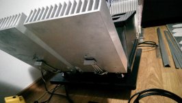
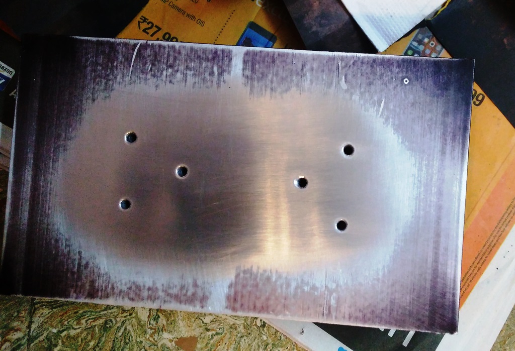
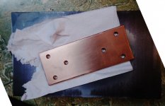
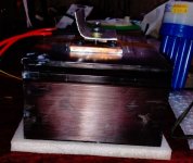
pics of radiators and copper heat spreader. still a work in progress. wet sanding starting with 320 grit to 1500 and finally with 2000- keeping in mind the shape of both the surfaces. it's takes lot of time and still better than the stock surfaces.
dimension of aluminium heat sink: height: 125mm, length: 215mm fin length: 75mm and it weighs little more than 2.5 kg.


i'm going to use insulating tape [kapton] between transistor and the heat sink. hopefully it should help as i'm planning to mount the radiators on to chassis directly. also my soft start kit comes with temperature sensors for each of the 2 radiators and they are rated for 75 Degree Celsius. i'm planning to mount these sensors closer to transistors to avoid any issue with over heating.
pics of radiators and copper heat spreader. still a work in progress. wet sanding starting with 320 grit to 1500 and finally with 2000- keeping in mind the shape of both the surfaces. it's takes lot of time and still better than the stock surfaces.
dimension of aluminium heat sink: height: 125mm, length: 215mm fin length: 75mm and it weighs little more than 2.5 kg.
Attachments

Last edited:
Hi Som,
Look at my modified super class a from the pics bellow. I have it for almost two years now and didnt have a problem with heat or thermal tracking even in the summer when its pretty warm in my listening room. The rads are insulated from the chasis earthing and the outputs are sticked directly onto the rads. Now you have to understand the temperature issue very clear if you want to prolongue the outputs life when you are runing 1.65A bias through them especially in the summer, when the rads run hot even through they are pretty big (in my case). Believe me that 1.5A its like a limit for the outputs and if you run the bias higher they will tend to run extremely hot. So please keep that in mind first as a caution that needs to be taken care.
Cheers
Sergiu
Oooh - like a satellite.
Exactly like a satellite.
ooh, 2 weeks amplifier was "online"?
) nope. I let the amp run continously for aprox a day in each case for two weeks in the summer and measure the temps at about two hours to see how different rads and radiator positions work at different periods in a day at high and lower temperatures respectively. I have tried another two smaller rads and these bigger rads in different configurations (verticall, 15degrees, 45degrees, horizontall, stack effect with different distances and with diffent orientations). Anyway my conclusion is that in the summer, the cooling situation changes drastically. It seems that when the room temp rises, the air flow between the cooling fins of the rads diminishez drastically thus the cooling diminishez. So to counter this effect i oriented the rads to maximize air flow and the 45 degrees orientation was optimum because of the big "exposed active area" (if i may say so) of the rads. This sollution also ensures a 45degrees position of the output capsules wich are oriented now with the face down wich ensures a uniform disipation area for the outputs. This chosen solution combined with the direct contact between the output tranies and the rads (with silver grease) ensures a healthy almost 14degrees celsius down for rads and a difference of 4~5 degrees between outputs and rads wich is a good thing considering that i want a long life for the outputs.Then i wanted more so i buyed fatter rads with taller fins and height. I used them in the same formula as described above and got a healthy 52degrees for the capsules and 47-48degrees for each rad at 24-25 degrees room temp.

I think that a new thread with cooling sollutions for class a should be opened and discussed and measurements posted there. I have searched allot on the web for different cooling sollutions but found very few results...

I hope that what i wrote here would help others.
Cheers
Sergiu
Hi Alex,
I also used mica but got a wopping 12 degrees difference between rads and outputs wich in my opinion is awfull. I dont think mica is so bad but it has to be extremely thin to get very good results. I think that the mica that i buyed from the local store (with no specs or datasheets) was abit too thick ..
Cheers
Sergiu
Hi Alex,
I also used mica but got a wopping 12 degrees difference between rads and outputs wich in my opinion is awfull. I dont think mica is so bad but it has to be extremely thin to get very good results. I think that the mica that i buyed from the local store (with no specs or datasheets) was abit too thick ..
Cheers
Sergiu
AlN.
Mica thickness is very variable.Hi Alex,
I also used mica but got a wopping 12 degrees difference between rads and outputs wich in my opinion is awfull. I dont think mica is so bad but it has to be extremely thin to get very good results. I think that the mica that i buyed from the local store (with no specs or datasheets) was abit too thick ..
Cheers
Sergiu
Much that comes cheaply are >5thou thick and a few are >9thou.
Kapton seems to come in 3thicknesses, 1thou, 2thou, 6thou.
Mica and Kapton have similar thermal resistance and when both have a very thin layer of thermal goop applied to both surfaces they become even more similar.
Aim for the thinnest of either 1thou Kapton, or <1thou Mica, with a good thermal goop that is minimum thickness.
Only few grades of Keratherm are better. Most silpads are worse, but some can match thin Kapton/Mica.
Hiraga Super 30W
hi all,
finally, i've hooked up the power supply with the amp board. it's been couple of days that i'm running the amp for about 2 hours a day.
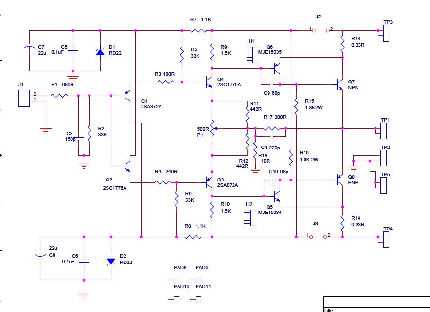
when i first powered it up, the Q current was more than 2 Amps! later with the inputs from a friend, i increased the bias resistors[R5 and R6] from 33K to 35.7K. now the Q current is between 1.58Amps to 1.78Amps depending on the mains voltage. after troubleshooting some noise issues speakers play excellent music! but there is a hum in the speakers when there is no music/source input. i.e. if i switch off my music player [Cowon S9] the hum is back and if i switch it on even without music being played, the speakers are completely silent - i can't hear any noise even if i almost press my ears to the speakers.
circuit [Amp PCB is from Jim's Audio]:
heat sink set-up:

i've few queries:
1. what might be the reason for the noise when no input is connected?
2. when i run the amp, i think heat sinks get really hot - i can't touch them with my fingers for more than couple of seconds. but this temperature seems to remain constant even at the end of 2 hours. heat sink size is more than 2.5Kilos per NPN/PNP. is this normal?
3. i see that my mains voltage fluctuates between 210volts in the morning[rail voltage of +/-27V] to 240+volts in the night[rail voltage of +/-29V] and this seems to have direct impact on the Q current [which stabilizes around 1.58 in the day to 1.78 in the night]. is this normal?
i would be getting my mono amp enclosure in a day and i'll be arranging/wiring the guts into it by the weekend!
PS: i think i've managed to burn one of my old speakers yesterday night which i was using for testing. music is all garbled and i can smell something burnt from the bass reflex holes : these are 2 way speaker off a Aiwa mini hifi system rated at 6 ohms came with the system that was rated for 30W RMS. i had not hooked up the speaker protection circuit : plan to do so before next power-up.
hi all,
finally, i've hooked up the power supply with the amp board. it's been couple of days that i'm running the amp for about 2 hours a day.
when i first powered it up, the Q current was more than 2 Amps! later with the inputs from a friend, i increased the bias resistors[R5 and R6] from 33K to 35.7K. now the Q current is between 1.58Amps to 1.78Amps depending on the mains voltage. after troubleshooting some noise issues speakers play excellent music! but there is a hum in the speakers when there is no music/source input. i.e. if i switch off my music player [Cowon S9] the hum is back and if i switch it on even without music being played, the speakers are completely silent - i can't hear any noise even if i almost press my ears to the speakers.
circuit [Amp PCB is from Jim's Audio]:
heat sink set-up:
i've few queries:
1. what might be the reason for the noise when no input is connected?
2. when i run the amp, i think heat sinks get really hot - i can't touch them with my fingers for more than couple of seconds. but this temperature seems to remain constant even at the end of 2 hours. heat sink size is more than 2.5Kilos per NPN/PNP. is this normal?
3. i see that my mains voltage fluctuates between 210volts in the morning[rail voltage of +/-27V] to 240+volts in the night[rail voltage of +/-29V] and this seems to have direct impact on the Q current [which stabilizes around 1.58 in the day to 1.78 in the night]. is this normal?
i would be getting my mono amp enclosure in a day and i'll be arranging/wiring the guts into it by the weekend!
PS: i think i've managed to burn one of my old speakers yesterday night which i was using for testing. music is all garbled and i can smell something burnt from the bass reflex holes : these are 2 way speaker off a Aiwa mini hifi system rated at 6 ohms came with the system that was rated for 30W RMS. i had not hooked up the speaker protection circuit : plan to do so before next power-up.
Attachments

Last edited:
- Status
- This old topic is closed. If you want to reopen this topic, contact a moderator using the "Report Post" button.
- Home
- Amplifiers
- Solid State
- Hiraga 20W class A