The ratio of re' to RE doesn't matter because it is the Ic swing that sets the harmonic generation across Re', and the Ic swing is the same regardless of RE.
If our VAS was voltage driven and the feedback loop did not keep the IC swing the same in all conditions in order to meet the output demands, then RE would decrease the harmonic generation of re' by reducing Ic swing (at the same time as reducing gain). But that is not the circuit that is on our bench.
The resistor does however increase the conversion of OPS drive current to voltage at the VAS input which CAN increase distortion, but luckily again our VAS is current driven so the effect is not very strong.
[...]
I have not once, ever, found the idea of "local feedback linearizing the VAS due to Miller capacitance or RE" to be helpful, and in fact every time I've seen it brought up it leads in totally the wrong direction. It's like a computer virus which hides itself by causing the CPU to skip over countless important error checks.
Hi Keane, this is probably one of the best posts I have seen in DIYAudio... not only because it is true, but it de-mystifies a lot of none-sense floating around.
So just to add my 2 cents here:
RE in the second stage (VAS)
As Keane correctly points out, for the second stage (VAS), all that matters for practical terms is the I-V transfer function, since the stage is configured as an integrator, driven by a high impedance (output of the Input stage). Also, distortion is purely proportional to the error current being drawn from the input stage output. So anyone who says that RE is needed to linearize the second stage voltage GM, does not know what he/she is talking about. I believe this wrong school of thought came from Cordell's book.
If fact, Sam Groner's paper as well as Keane's note above points out that having RE is detrimental to distortion. The mechanism is as follows:
- The RE resistor increases the conversion of OPS drive current to voltage at the second stage input which is non-linear (Delta VBE + RE x Non-linear OPS input current)
- The second stage input voltage, which is non-linear, creates a feedforward current through the Miller cap (CM)
- This feedforward current is non-linear and has to come from the input stage
- This generates a non-linear voltage across the LTP's input terminals which gets multiplied to the output by the amplifiers gain.
Since the feedforward current increases as the CM impedance decreases over frequency, this distortion mechanism increases over frequency. Therefore, it will be hardly present at 1K, but if you have a low distortion amp, it will manifest at 20K.
So why do reason most amps have an RE in the second stage? This is two fold:
- It makes it easy to implement second stage current limiting
- It stabilizes the second stage minor loop formed by the Miller cap.
... and well, people don't know the effect mentioned above
")
2. Local feedback linearizing the VAS due to Miller capacitance or RE
Yes and no.
The Miller capacitance linearizes the second stage by forcing its I-V transfer to be 1/sCM, but does linearize what actually matters for distortion. Therefore, explaining distortion from the point of view of the Miller cap linearizing the second stage is fairly useless. This poor explanation of second stage distortion comes from Doug Self.
Recognizing that what matters for distortion is the error current drawn from the input stage output, the linearizing feedback from CM does not address the following errors:
a.- IB from the buffer transistor which in turn has the following sub-errors:
i.- Output stage input bias current current or load current on the second stage divided by beta^2 (assumes a 2 transistor/darlington circuit)
ii.- the IB of the CE transistor in the second stage which is due to Delta VCE, Delta IC and the above
b.- The input voltage of the second stage being modulated... see [1]
c.- Baker clamp, where in non-clipping conditions, its non-linear capacitance adds to CM which is the 'feedback path' of the second stage loop.
Again, awesome post Keane, please keep it up!
P.S. re + RE terminology Stuart uses cames from me... that is typical Op-amp design terminology.
Last edited:
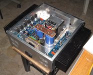
Okay, she's running both channels. Still on the cheap test speakers for a few day, but the control is pretty nice. The poor lab speakers can only handle a fraction without starting to buckle.
I've been using amps under 30 watts for so long I forgot how good something with power to spare can be. I usually don't listen to loud, but when I do I can hear the lack of spare power.
This will be an amp that I crank up when I feel like making the walls breath.
I've been using amps under 30 watts for so long I forgot how good something with power to spare can be. I usually don't listen to loud, but when I do I can hear the lack of spare power.
This will be an amp that I crank up when I feel like making the walls breath.
I made some choices with new info, so I would say it's something like a 2.4X. At this point, I don't even remember all the changes I made, so don't ask me to recount them. I will say most were made with alternate parts and then more alternate parts to make those work right, or at least right according to my limited knowledge. I guess I did something right, cause it's running.
When I heard about the new version, mid build, I almost put it on hold, but at that point I had so much time in I decided to go forward. That said, depending on some testing and listening, that's not to say I won't pull the boards and build the new version as well. Also, I might just build the new one and put them on the bench for some side/side, I'm sure others have that thought as well, so it's just spitball at this point.
We are coming up on summer and I feel like it's been two years since we had a proper one, so building is likely going to get pushed back for outdoor activities.
EDIT: One thing I like to see in any design is boards that I can mount the same way on both sides... The Badger doesn't do this... say I want both input section at the rear of the sink, I have to mount one of the boards upside down, which crested a hole other set of problems. I like to keep my input runs short, so I want both to the rear of the case. I don't want to run and input 14 inches tot the board, ya'll know why. So let's make them so I can keep the same orientation from left to right and the in/outs are se-metrical. PLEASE!
Last edited:
Tried to edit typos, but was shut down, by the 30min admin rule. Can we do away with that too for supporting members?
JT
you can report your own post to request for a moderator to edit....
Ok question, some may find it stupid, but... How the hell do I upload a Bom file to digikey Canada, every time I do it it only does the top of the excell file that is on the badger parts list ? Any help would be greatly appreciated, I just got my board in the mail and wanna start building !! Also want to put some sort of speaker protection and soft start, how is the ones that diy has?
And also how is the diy universal power supply? Thanks again!
And also how is the diy universal power supply? Thanks again!
Universal Power Supply is great, and it was easy to assemble as well. I broke off the diode board, and opted for monolithic bridge rectifiers instead.
If you tell the group a little bit about your build(transformer size, voltage, outputs, etc.) , I'm confident someone can help you with the soft start/ speaker protection. I built the store units for those options as well, but they weren't optimal for my power requirements after all. I will probably use them in a future project, as they are pretty good quality as well!
As for the BOM... I ended up putting mine in manually!
EDIT: One thing I like to see in any design is boards that I can mount the same way on both sides... The Badger doesn't do this... say I want both input section at the rear of the sink, I have to mount one of the boards upside down, which crested a hole other set of problems. I like to keep my input runs short, so I want both to the rear of the case. I don't want to run and input 14 inches tot the board, ya'll know why. So let's make them so I can keep the same orientation from left to right and the in/outs are se-metrical. PLEASE!
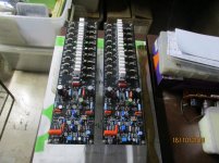
this is how i mounted boards in my amp....
Attachments
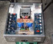
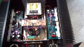
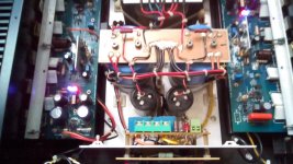
Ya, I know, one or the other input will have to run 10 inches or more inside the case. With all the stuff I have in mine this is less than optimal. In fact, I have had great results with amps people say need special care for shielding and other measures which were not needed, by keeping the layout as clean as possible.
There is no reason the boards can'r be designed, so that they are oriented the same way.
It's not a deal breaker, but if you think about it, it makes sense from many directions and simplifies the layout....
Just sayn
There is no reason the boards can'r be designed, so that they are oriented the same way.
It's not a deal breaker, but if you think about it, it makes sense from many directions and simplifies the layout....
Just sayn
Test Results
Hi Keantoken,
Well after a many days of testing and trying many, many options
I found the following.
My final values for the following components are.
C7 = 56pf
C8 = 330pf
R23 = 10 ohms
R36 50 ohms
R15/16 = 130 ohms
R22 = 470 ohms
R14 = 1.3K
Thank you for your suggestions keantoken's
I have labeled the filename as a brief description of the test setup.
I have also left notes in the images for everything else.
Conclusion.
Even though I was able to increase the unity gain crossover frequency from 860Khz to 1100Khz and still maintain a healthy 86.5 degrees phase margin. I was not able to reduce the 16Khz distortion. There must be another distortion mechanism in place that is swamping the OPS distortion
There is one last photo showing Test setup 9. I simply measured the
distortion at the VAS output node at 16Khz and it was 10x lower that at the Vout node. Given the NFB was not taken from the VAS output node but it still indicates significant distortion is coming from the OPS. I did of course experiment with all levels of Bias levels and found 48mv between TP1 to TP2 to be the best.
Keantoken, Do you have any idea's on what I could look at to help explain the increase in distortion at 16Khz and my inability to reduce it?
Thanks for your support.
Stuart
Attachments
Hi Kay Pirinha, check test setup 8 and 9 as well as the file that shows the distortion plot using old and new transistors.Hi Stuart,
why did you remove those »old transistors«? Were they defective? And what did you swap them for?
Best regards!
The filename for test setup 8 and 9 has the transistors types.
Basically the new transistors MJL4281A and MJL4302A were installed as a test to see if they would produce lower distortion then the standard mjl0281/mjl0302 as the have a high beta and higher FT value.
But as you can see from the distortion plot they made no difference. So at this stage I'm assuming because there is another distortion mechanism that is dominating the distortion.
- Home
- Amplifiers
- Solid State
- diyAB Amp - The "Honey Badger"