Or ask questions, get answers.
As mentioned before, the DC voltage will end up at about 55 V with your transformers (or maybe a bit lower). The 63 V rating should do it, although some may say that more margin would be better. But with this PSU already available I would just give it a try.
Yes , and no . Maybe some the simple one. At least you need gear a full elec. lab
Andrew T did not get it working ( In memory of) .
Of course help can be provided , heltim asked a lot in a good way.Anyway
Im a tech. in analog electronics & EDP. (True)
Answers like AC to DC voltage mbrennwa answered , so basics. Should someone answer
a question so basic . If so read about passive components, check data sheets same with active semiconductors. Practical electronics , run electodroid or similar app to ease , calulate basics . Running into brick wall then ask.
Matching bjt. DC & AC analysis prefered at
Now mbrennwa have you completed HB .& as build guide or own choice.
Why use PCB with golden tracks when the guide do not. Should be asked !
Disadvantages: of electroless nickel immersion gold (check out if unknown).
Solder Joint Reliability of Gold Surface Finishes (ENIG, ENEPIG, DIG)
Now mbrennwa have you completed HB .& as build guide or own choice.
Yes, I have. And I got some good help our of this forum. Just search this thread and also the HB build thread.
with 55v ac, i will use a 100 volt dc cap and no worries...
55 volta ac is 77 volts rectified, even the 80 volt cap is iffy....
when your nominal 230 volt mains rises to 250 volts, that will hit you..
He's been speaking of 2 x 37 VAC...
Best regards!
exactHe's been speaking of 2 x 37 VAC...
Best regards!
") 600w 2x37v AC
600w 2x37v ACHe's been speaking of 2 x 37 VAC...
Best regards!
so in this case, i will use 63vdc caps...
 !
!Hi All,
I'm in the planning/purchasing stage of a HB build. One mod I'd like to try is a capacitance multiplier between the OPS rails and the IPS/VAS. I found a well known design
One question. In the SM design, there is an RC stage upstream from the multiplier. Can I safely ignore that ? (There are a couple of loads there in the SM that don't exist in HB).
Also, apart from the R22/R23 ratio, are there any crucial component values in the multiplier circuit ? Anything need to be changed for the HB application ?
Any good reasons why I should NOT do this ?
FWIW, I'm looking at OPS power rails around 42 volts, so 40-ish after the multiplier. (I'm a sonic sissy - no loud music chez moi.)
Thanks
PS #1 No I didn't forget about the negative rail !
PS #2 If this would be better in the build thread, find a kind and gentle way to let me know.
MTA : Although I circled the output bypass cap (HB c10, SM C5) I would physically mount that one on the HB board, not on the perfboard.
Can someone help? Referring to the attachment (on the right side) of the quoted post, what should be the minimum voltage rating of C7/C10 of the cap multiplier circuit for 42V supply?
Can someone help? Referring to the attachment (on the right side) of the quoted post, what should be the minimum voltage rating of C7/C10 of the cap multiplier circuit for 42V supply?
Those will see a couple volts less than rail voltage so 50V+
Those will see a couple volts less than rail voltage so 50V+
Thanks Jeff.
LT Spice version XV11 does have problems crashing often with Win10 I believe. I run Win8 and have occasional crashes, it mostly happens if I hit "run" without saving first.
I haven't run into this , linux OP system mostly under wine, Virtualbox running Win8 or 10 .
Hello,
I think about may be building the honey badger the next time.
Want to use a broken Yamaha MX70 (one CH went up in smoke).
Use the Chassis maybe the transformer if it fits and so on...
So here is my question:
How would be the Badger in comparision to the yamaha mx70? have someone heard the both amps?
Because i also think about to repair the Yamaha and quit the badger.
do not really know what i should do????
Thanks for suggestions,
Alex
Smoke and sparks
Started my first test Power supply measures spot on at 63.8 volts both sides. Installed my two 10 ohm resistors in place of the two fuses turned on the power and r54 went up in smoke One thing I found later is if I put my continuity meter on a any C terminal of the transistors and the heat sink frame I have connection and other ground spots. Is this normal? I did my test without any soft start or surge protection ( cl-60 will be here in a couple days)
Started my first test Power supply measures spot on at 63.8 volts both sides. Installed my two 10 ohm resistors in place of the two fuses turned on the power and r54 went up in smoke One thing I found later is if I put my continuity meter on a any C terminal of the transistors and the heat sink frame I have connection and other ground spots. Is this normal? I did my test without any soft start or surge protection ( cl-60 will be here in a couple days)
Attachments
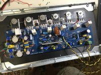
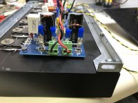
You shouldn't have any continuity between the collectors of the output transistor and the heat sink. Do you have insulators under the washers on Q14 and Q15? Are the screws touching the tabs on the transistor?
You should be using a bulb limiter at the very least for meltdown protection on start up.
You should be using a bulb limiter at the very least for meltdown protection on start up.
- Home
- Amplifiers
- Solid State
- diyAB Amp - The "Honey Badger"