Fusing depends on your choice of supply transformers. Sounds like you have too much current flowing somewhere. An undersize fuse may blow when initially powering up but once the amp is idling it should draw next to nothing. Do yourself a big favour and build a bulb limiter. Amplifiers will stink up your whole house when they go up in smoke!
Look if Q15 is fine. What makes honeybager a amp, to have, , learning ostippers tricks dual seconeries dual Mono Somewhat easy to get to work to the driver stage.
Many in the beginning reported amp working, later not so much.
Terry's favorite at time, similaratys to some degree HK 6xx series. Guide made by Jojo who liked Irfp240 9240 by apex just as all audio fanatics Own pcb of course, slewmaster more stabile by osripper words than ef2 Honeybager.
Well diy audio wanted ostippers to do pcb will there 2.5 well it's diy after all. Many have liked this amp.
Yngvejos showed clipping befaviour in his amp. As terry
Jwillhew do you have you done the honeybager or plan to . You could do the V. 2.5 with protections store could be happy as customers with their amps. It could be a hit.
Ostripper was a recycling guy, 20€ for amp. Even Mr. Xr has not done this amp maybe he will.
Hi tonza75,
So I guess you have built a Honeybadger then?
Pete isn't here to defend himself, and your comments do not reflect my personal experiences with communicating with Pete. Since I highly doubt you have, I'd say you are speaking out of turn. Therefore I have to ask, what is the purpose of your attack on this amplifier and it's creator? Before commenting you might want to actually build the amplifier and test it. If you aren't interested in doing that you have no business in this thread at all. Best move along to something that you are interested in.
-Chris
Good advise , 1 channel "ok" nothing personal meant, pete the guy many loved, including me , bike tour i support fully.Moved on.
Yes true best moving to something else i like. Ltspice creator not attacked.Licensed or not.
Ok , how many have you built anatech of honeyB .
Yes true best moving to something else i like. Ltspice creator not attacked.Licensed or not.
Ok , how many have you built anatech of honeyB .
Hi tonza75,
One in process as I find time.
Many times we look for "the best", yet the less evolved designs can sound quite good.
I built a bunch of Symasym amplifiers earlier. They were modest, but with some care in matching parts and using better component types they sounded far better than I expected. You just never know what design can sound great. They measured fairly well also. Maybe one of these days I'll pull one and measure it again.
-Chris
After smoking my amp by forgetting the plastic washers I have replaced damaged resistors and Q13 thru 15 all tests work except setting at r30 variable resistor giving me only 4 millivolts at speaker output. Any ideas where to look next?
+-100mV is criteria, yours is acceptable...

the thing is look at your speaker cones when connected, does it weer away from dead center much?
if the amp has an output offset nulling pot use it to get as close to 0 volts, otherwise if there are none, then +-100 is acceptable...
what else can you do? match the input ltp trannies, but this is extra work...
if the amp has an output offset nulling pot use it to get as close to 0 volts, otherwise if there are none, then +-100 is acceptable...
what else can you do? match the input ltp trannies, but this is extra work...
Instructions call for 20 to 25 mvolts
I think that's the bias current measurement taken across the emitter resistors.
Here's a quote from the setup instructions.
"Adjusting this is simple. R30 (BIAS) should be set to 500R (read it with your DMM). This will forward bias Q13 to the max and make
the voltages across C9 their smallest , biasing the output stage to class B levels. Slowly turn R30 until you see your first
few millivolts across TP1 and TP2. Continue until the test points show 15-20mv , allow to thermally stabilize ... adjust further.
Note: Some like it "hot" (30-40mv = 100ma/ per device) , some like it "cool" (20-25mv = 50mv) crossover distortion usually minimizes"
Connect each lead of your volt meter to TP1 and TP2, not the output. Then set R30 to read 20 - 25mV.
the thing here as with all amps, the 1 watt level, i.e. 2.8vac into an 8 ohm load,
is checked for notch distortion, bias your amp so that the zero crossing is very smooth,
do it with the smallest bias current that you can get away with...
while more can lessen THD, but then the idle dissipation may be high and if your heatsinks are not up to it heating the output trannies is the net result...
crossover distortion....
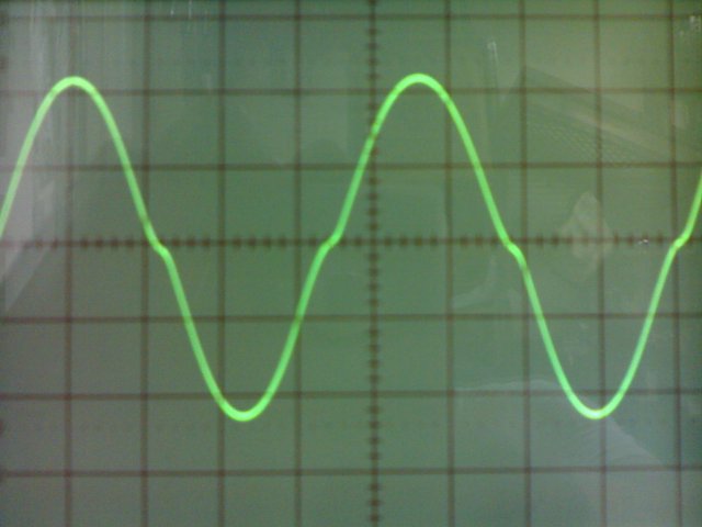
clean sine wave:

is checked for notch distortion, bias your amp so that the zero crossing is very smooth,
do it with the smallest bias current that you can get away with...
while more can lessen THD, but then the idle dissipation may be high and if your heatsinks are not up to it heating the output trannies is the net result...
crossover distortion....
clean sine wave:
A 4 mV DC offset is excellent without a servo. A 0 mV DC offset doesn't buy you anything over what you have.
In many cases I won't correct a DC offset (without adjustment) unless it goes over 50 mV. Some designs actually have a designed in DC offset of over 100 mV, and I have seen 250 mV DC offsets designed in (poor design actually). So, you can see you have nothing to be concerned over.
Just for the sake of interest, measure the DC offset with the amplifier cold (just turned on for the first time) and again at 1/2 an hour. You can make notes of the offset more frequently if you want. The interesting thing would be to see how stable the DC offset is with operating temperature. Idling is fine here, no need to actually run it into speakers.
Heat shrink tubing is normally what I use to hold the pairs together as it also creates a barrier to the ambient air and helps the pair maintain a more equal temperature between them. I have seen plastic caps over that, or even foam if the diff pair doesn't dissipate much heat.
-Chris
Hi Tony,
That is an excellent photo of crossover distortion. Really brings the point home.
-Chris
yes, Chris, after all the whole point of this biasing exercise is to get rid of this notch distortions that are quite audible at low volume levels....
bias only what is needed to rid this distortion, this is the whole point of biasing..
- Home
- Amplifiers
- Solid State
- diyAB Amp - The "Honey Badger"