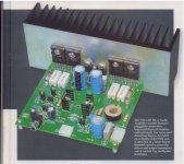
The circuit has:
- PNP input with mirror output
- Darlington VAS
- MJE15030/31 drivers of
- 2 Thermal Trak pairs for output
All is pretty standard for getting high Open Loop Gain
in a blameless topology.
What is 'extra' is the Thermal Trak for good current control.
The amplifier's concept has been tested good many times before.
With a good power supply, I am sure this amplifier is worth the money")
- PNP input with mirror output
- Darlington VAS
- MJE15030/31 drivers of
- 2 Thermal Trak pairs for output
All is pretty standard for getting high Open Loop Gain
in a blameless topology.
What is 'extra' is the Thermal Trak for good current control.
The amplifier's concept has been tested good many times before.
With a good power supply, I am sure this amplifier is worth the money
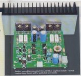
The circuit has:
- PNP input with mirror output
- Darlington VAS
- MJE15030/31 drivers of
- 2 Thermal Trak pairs for output
Changes from the mk2 version:
Only 2x thermaltrak diodes used
2 pole compensation
vbe multiplier and bias trim adjustment
really big cap in the fb network
lower pole frequency input filter
Adds up to - more consistent performance and low measured THD above 2kHz and below 50Hz.
Hi There,
Thanks for the heads-up
I'm a big fan of the MK 1 (stereo kit) which I converted to 'power amp only', and mono-block with custom aussie made transformers,, Sounds great!!
I have no personal experience with the MK 2, but feedback I've always heard is that MK 1 was far superior than the MK 2.. So it will be interesting to see (hear) how Mk 3 compares to MK 1 ??
Thanks
Murphy
Adds up to - more consistent performance and low measured THD above 2kHz and below 50Hz.
Have you checked the clipping performance? With 2 pole compensation your fellow countryman GK mentioned there were a few caveats somewhere on this forum.
Changes from the mk2 version:
2 pole compensation
Adds up to - more consistent performance and low measured THD above 2kHz and below 50Hz.
I thouhgt they used TMC , but no , they choosed a less stable method..
Dont they visit DIYaudio sometime ??..

I thouhgt they used TMC , but no , they choosed a less stable method..
Dont they visit DIYaudio sometime ??..
maybe they read and understand my posts on the issue - TMC is not "more stable"
post #1333: http://www.diyaudio.com/forums/soli...lls-power-amplifier-book-134.html#post2420438
Last edited:
Nicholas does visit us from time to time and I'm sure he will take note of comments.
But to be sure I will forward a link to his e-mail address.
Well, it s funny since a version of this amp was discussed by there
and even simulated to see what improvement would bring TMC..
http://www.diyaudio.com/forums/solid-state/142166-new-amplifier-uld-extreme.html
http://www.diyaudio.com/forums/soli...-popular-amps-simulations-18.html#post2313030
maybe they read and understand my posts on the issue - TMC is not "more stable"
Perhaps when computing according to a model with idealized components,
but so far , all the simulations i did showed that generaly TPC is less stable
with capacitive loads, for some logical reasons..
match the high frequency loop gain curves as properly measured around the output devices, "inside" the TMC network and the stability properties are going to be very similar - for well understood engineering reasons...
you may notice several others in the Cordell Book TMC discussion thread made good cases for the essential similarity of 2-pole, TMC
also http://www.diy-audio-engineering.org/forum/index.php?topic=26.0 thread - but drawings, attachments not visible to non-members
the loop gain matching isn't done by simply rearranging the same valued compensation components between 2-pole, TMC
Last edited:
match the high frequency loop gain curves as properly measured around the output devices, "inside" the TMC network and the stability properties are going to be very similar - for well understood engineering reasons...
You mean: you don't get something for nothing.
If you raise the olg above 20kHz by 20dB you are going to compromise stability regardless of method.
I have modified a mk2 version of the amp and it uses mostly TMC but also a bit of CMC. With an extra 20dB of 20kHz OLG thd is obviously very much reduced.
I favour TMC over TPC based on comparisons between the +ve slew rate - as well as my ears that tell me TMC sounds better with this design.
Look also this thread:
http://www.diyaudio.com/forums/solid-state/188133-tmc-tpc-my-dilemma-resolved.html
dado
http://www.diyaudio.com/forums/solid-state/188133-tmc-tpc-my-dilemma-resolved.html
dado
No longer impressed.
Is this amp 6 ppm THD20 ? At what output ? 6ppm is not hard to achieve these days. But can it "hold" that @ 100v p-p 20Khz ? 4R , anyone ? . If it's not a triple , highly doubtful ....
It does look like a nice build. Sporting those T-traks and using a real Vbe + 2 of the internal diodes must make for near perfect thermal response. Still , it is what it is.
PS - I can now beat TMC ... without TMC ( 2 designs).
OS
Is this amp 6 ppm THD20 ? At what output ? 6ppm is not hard to achieve these days. But can it "hold" that @ 100v p-p 20Khz ? 4R , anyone ? . If it's not a triple , highly doubtful ....
It does look like a nice build. Sporting those T-traks and using a real Vbe + 2 of the internal diodes must make for near perfect thermal response.
Still , it is what it is. PS - I can now beat TMC ... without TMC ( 2 designs).
OS
Last edited:
match the high frequency loop gain curves as properly measured around the output devices, "inside" the TMC network and the stability properties are going to be very similar - for well understood engineering reasons...
the loop gain matching isn't done by simply rearranging the same valued compensation components between 2-pole, TMC
Agree, but then most of the TPC advantages will be lost.
Although the result is better than classic miller comp THD wise,
it s inferior to TMC when looking at both THD and stability.
Is this amp 6 ppm THD20 ? At what output ? 6ppm is not hard to achieve these days. But can it "hold" that @ 100v p-p 20Khz ? 4R , anyone ? . If it's not a triple , highly doubtful ....
It does look like a nice build. Sporting those T-traks and using a real Vbe + 2 of the internal diodes must make for near perfect thermal response.
PS - I can now beat TMC ... without TMC ( 2 designs).
OS
Rated power, 8 ohms, 1kHz.
THD does degrade to 20ppm at 10 kHz but the reason is (apparently) due to minor limitation in the layout of the speaker traces. There will eventually be a mk4 to address it but we'll need to wait. However, there's nothing to stop constructors from routing the speaker earth return close to the rail feeds, and locating the output inductor further away from the vas.
I read the mk2 had some blowup issues attributed to the VAS Q8 not being current-limited, SC added a 22k resistor on the (grounded) collector to fix. Scary that this mod and a few others don't appear on the SC website. Hopefully addressed in the mk3.
Looking forward to my issue arriving, postal strike here sucks.
Looking forward to my issue arriving, postal strike here sucks.
I read the mk2 had some blowup issues attributed to the VAS Q8 not being current-limited, SC added a 22k resistor on the (grounded) collector to fix. Scary that this mod and a few others don't appear on the SC website. Hopefully addressed in the mk3.
Looking forward to my issue arriving, postal strike here sucks.
It had several non solved issues, dont know to what extent these
were solved in the current version..
- Status
- This old topic is closed. If you want to reopen this topic, contact a moderator using the "Report Post" button.
- Home
- Amplifiers
- Solid State
- Silicon Chip ULD Mk3 amp - 0.0006% distortion