Hi Mike,
interesting observations! So I Start asking myself: What would be the sound advantage of SSR over relay contacts? What’s the difference? Sorry, I did not read the whole thread...
Greetings,
Winfried
In this case it's not about "better sound."
It's about avoiding degrading the sound by not having worn mechanical contacts in the signal path...if a very high quality (read: expensive) mecanical relay isn't used (and sometimes even when one is used), increasing levels of distortion over time is nearly inevitable.
It's also a matter of reliability. A high current fault, such as an output stuck to one of the power rails causing a large amount of DC current to flow into the output node, can actually weld relay contacts together and prevent it from breaking the connection...that would be bad.
Mike
I totally agree. For this reason I start this thread sometimes agoIn this case it's not about "better sound."
It's about avoiding degrading the sound by not having worn mechanical contacts in the signal path...if a very high quality (read: expensive) mecanical relay isn't used (and sometimes even when one is used), increasing levels of distortion over time is nearly inevitable.
It's also a matter of reliability. A high current fault, such as an output stuck to one of the power rails causing a large amount of DC current to flow into the output node, can actually weld relay contacts together and prevent it from breaking the connection...that would be bad.
Mike
Line-up (Overview) of Vintage Receiver Models with AC Speaker Output (not DC) wanted
If there are electrolytics between output power amp and speaker terminal in use like that under
Mundorf - Inner Excellence
there is no unwanted audible effect present with simultaneous DC protection without relay contact. Only the additional 6db high-pass function has to be taken into account.
....It's about avoiding degrading the sound by not having worn mechanical contacts in the signal path...
Mike
Well I can vouch for the mechanical contact issue. I'm rebuilding a mid-70's 200W/ch amp. Thought I was all done until I discovered about 10x distortion increase when I ran the output through the 70C thermal fuse contacts. Hopefully new ones will resolve that. If not I'll figure out another way to do it.
I switch the speaker ground on the nx-Amplifier protection board
BUT
If you short the speaker directly to the chassis, the SSR is bypassed so you have no protection in that eventuality.
Perhaps, but what I'm wondering is if that eventuality is even physically possible at all, depending on how things are effectively arranged mechanically.
For example, if the amp's output plug resides right on the pcb and there is no wiring at all, and the plug has a plastic casing, I don't see how it could be feasible to short the amp's output to the chassis that way. Can it? If so, how?
On Bridged amps you only need 1 SSR but you have to take protection inputs from both amps so that if either fails, the SSR is activated.
That's in case an amp fails, but what about the other things like shorts on the way to the speakers? Someone runs over the speaker cable with something heavy and sharp that cuts into the cable and bam!!
I would also like to add SSRs on the rails as well. I think that would be a plus, not for the eventual shorts on amp's outputs, but in case an amp fails, this would curb a bit the pulse from the reservoir caps.
You guys really should take a look at my posted circuit. I'm using the Si8752 FET driver, it's NOT PhotoVoltaic based, it uses an internal RF generator/reciever that is capacitively coupled. (Data sheet) https://www.silabs.com/documents/public/data-sheets/Si8751-2.pdf [/URL] It provides greater drive current for quicker switching speeds than any PhotoVoltaic type, and it's rated for use with high current applications such as mains switching. There's also the Si8751 version which is digitally controlled.
Rod Elliott posted an article on his site about it here: Project 198
Mike
Compared with something like VOM2171, Si871/2 does not really look better, different yes, but that is not a selling point in itself.
Compared with something like VOM2171, Si871/2 does not really look better, different yes, but that is not a selling point in itself.
I have done some comparative measurements on the Si8752 and the VOM1271 and I have to agree. The Si8752 output voltage was slightly higher at about 10 volts Vs about 9 volts from the VOM1271, so either had more than enough to saturate nearly any modern MOSFET to fully on. More importantly, the output current of the VOM1271 was was more than twice the output of the the Si8752 at around 50 microamps with 30 mA of drive current, so switching times will be quicker with the former rather than the latter. I am using the Si8752 for mains switching, which it has been Hi-Pot certified for, and the VOM1271 for switching DC power and speakers in my current project. I typically parallel the outputs of two MOSFET drivers to achieve faster switching times.
Mike
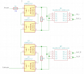
I am going to use VOM1271 and BUK9K29-100, is this schematic OK?
First, what are you using it for, and how much current are you driving the VOM1271 LEDs with?
Second, lose the 10 meg resistor, the VOM1271 has its' own built-in turn off circuitry, the resistor will degrade switching time which is important for minimizing the power dissipation in the MOSFET(s).
Third, I recommend you parallel the MOSFET driver outputs rather than series, more drive current will switch the MOSFET(s) faster.
Mike
This will be used for speakers. The source voltage is 12V, I am driving LEDs in series with a 300R/1W resistor, LEDs current is supposed to be 21mA @1.4V LED forward voltage which yields an output voltage of 8.7V to drive the MOSFETs.
Looking at BUK9K29-100 datasheet, the required Vgs is 10V to fully open these treansistors, this is why I used a series config, is 8.7V okay with these transistors?
Looking at BUK9K29-100 datasheet, the required Vgs is 10V to fully open these treansistors, this is why I used a series config, is 8.7V okay with these transistors?
This will be used for speakers. The source voltage is 12V, I am driving LEDs in series with a 300R/1W resistor, LEDs current is supposed to be 21mA @1.4V LED forward voltage which yields an output voltage of 8.7V to drive the MOSFETs.
Looking at BUK9K29-100 datasheet, the required Vgs is 10V to fully open these treansistors, this is why I used a series config, is 8.7V okay with these transistors?
Look again at the BUK9K29-100 datasheet, Rdson @ 5 volts is 25 mOhms, @ 10 volts it's a little less than 23 mOhms...no practical difference.
Mike
Does "parallel the MOSFET driver outputs" also works well for the drivers that have turn-off function built-in?
Do you have a reason to believe it wouldn't? My tests haven't shown any problems.
Mike
I would also suggest using one VOM1271 per MOSFET pair.
Two VOM1271 outputs in parallel will increase switching speeds.
Mike
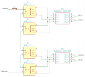
schematic modified to run VOM1271 in parallel.
10MOhm resistors removed.
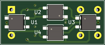
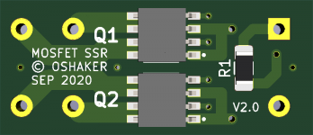
This is a 4-layer PCB, it fits in place of the Finder 40.52 relay so that I can use a normal relay or just the MOSFET SSR in my amplifier DC/SHORT protection.
Inner layer 1 is VCC, while Inner layer 2 is GND.
10MOhm resistors removed.
This is a 4-layer PCB, it fits in place of the Finder 40.52 relay so that I can use a normal relay or just the MOSFET SSR in my amplifier DC/SHORT protection.
Inner layer 1 is VCC, while Inner layer 2 is GND.
Attachments
Last edited:
Nice work. With 12 volts minus the cumulative voltage drop of four VOM1271 LEDs in series the current limiting resistor of 620 Ohms will only give about 10 mA of drive current. I recommend reducing it to 220 Ohms to increase drive current to 30 mA for faster switching speed.
Mike
Mike
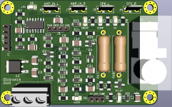
Hey Folks,
not understanding too much about SSRs, I'd like to verify the schematic I had received from a friend, which I use successfully in a Receiver as Output Relay replacement:
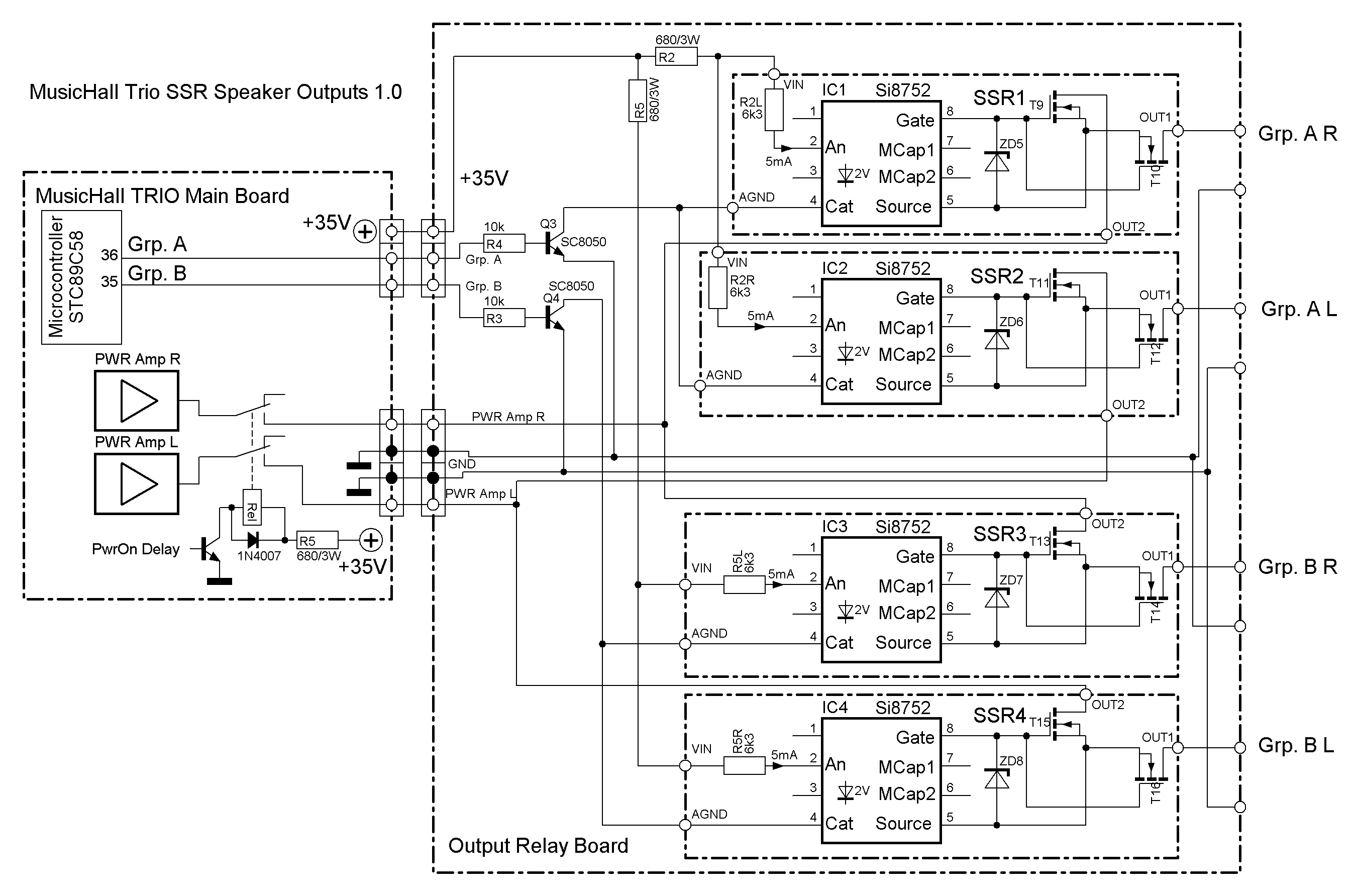
As I said, the circuitry works reliably, but I would be grateful to understand its potential advantages and disadvantages. Thanks a lot for the evaluation!
Regards,
Winfried
not understanding too much about SSRs, I'd like to verify the schematic I had received from a friend, which I use successfully in a Receiver as Output Relay replacement:
As I said, the circuitry works reliably, but I would be grateful to understand its potential advantages and disadvantages. Thanks a lot for the evaluation!
Regards,
Winfried
Attachments
- Home
- Amplifiers
- Solid State
- Output Relays