I just had an interesting idea. (lol)
One could also add a 2nd relay that switches an R-C + diode in parallel with the contacts of the 1st relay.
At breaking, relay 1 goes first, then relay 2.
(for folks who enjoy a lot of clicking noise
 )
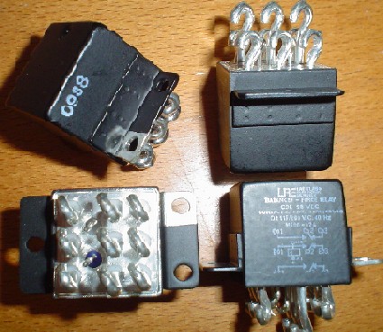
)Me doubt that the LRZ relay can handle 900W DC.
Bonsai,
When I wrote: "Only possible disadvantage is the small Rds could very slightly decrease damping factor at amplifier output, and the MOSFET's Rds will vary a tiny bit depending on current level though them, but after extensive listening tests I've never heard any audible artifacts of any kind." I was trying to say was there are no real issues with Rds, it's such a small resistance, in most cases probably less than the speaker wire, that it's really a non-issue. Besides, did you consider what would happen to an amplifier when the feedback loop was opened that way? It would't be pretty.
Mike
There are clever designers who have already solved this problem and the solution/s are posted in this Forum.consider what would happen to an amplifier when the feedback loop was opened that way?
Andrew,
Once agian, I don't consider Rds a problem, I'm kind of sorry I even mentioned it. The Rds of the IRFZ48V shown in the schematic is .012 ohms at 48 amps, truely insignificant. I've been using this circuit for years, and have never had any performance issues or sound degradation of any kind.
If anyone want's to try it for themselves, it's very easy to do. All you need is four power MOSFET's for stereo, with adequate voltage and current ratings and low Rds, driving the gates with a 9 volt battery through a large value resistor (100k to 1meg range should work OK) instead of the MOSFET driver. Try it, you'll like it!
Mike
Art M,
Those aren't steering diodes, in fact, if everything is working right, they do nothing at all.
Mike
I just quickly looked at the driver output internal diodes and assumed they may have been in the photoconductive mode . The PVI5013R diodes are being used in the photovoltaic mode. 1ua output is minuscule, but sure is enough for turning on a FET.
If you look at the IRFZ48V you can see that only one at a time can conduct on an AC signal.
You can't just reverse Source to Drain polarity and expect proper operation. Diodes serve as steering for proper operation ( =distortion). They also do back EMF duty as you pointed out.
Last edited:
Art,
Once agian, those are not "steering diodes". They are functionally out of the circuit unless something goes wrong, circuit works fine without them. Also, when the MOSFET's are saturated (turned on) they basically turn into low value resistors, there is no polarity, they conduct current equally in either direction.
Mike
Mike is right. There was a design maybe 20 years ago using several of these SSR in series, each with a parallel resistor, and was used as a (crude?) 100v line variable attenuator. The voltage drop of the body diode of each MOSFET is reduced considerably when the gate voltage is applied, in the same way that channel resistance is reduced in the normal mode of operation. Modern MOSFETs are even better wrt on resistance, and a photovoltaic opto eliminates possible modulation effects.
For my high power amps (+/-85V up), I use Potter & Brumfield (Tyco) KUEP series relays.
They are used in electric utility substations (which have 125VDC power systems) and locomotives. They are big and ugly but have built-in arc-quench/blowout magnets to give them a high DC interrupt rating (10A/150VDC) http://www.te.com/catalog/products/en?q=kuep
They are used in electric utility substations (which have 125VDC power systems) and locomotives. They are big and ugly but have built-in arc-quench/blowout magnets to give them a high DC interrupt rating (10A/150VDC) http://www.te.com/catalog/products/en?q=kuep
Hi all,
Just realized that another way to use these solid-state relays would be to pair them up with a standard mechanical relay. Imagine having SSR and mechanical contacts wired in parallel, with the SSR activating first at turn on, then the mechanical, and vica-versa at turn off. That way, the SSR would do the actual switching and the mechanical would short across SSR to bypass it. That way any concerns about possible signal degradation would be eliminated, and mechanical contacts would never be subjected to switching currents, no arcing -burning-welding problems, best of both worlds.
Mike
Art,
Once agian, those are not "steering diodes". They are functionally out of the circuit unless something goes wrong, circuit works fine without them. Also, when the MOSFET's are saturated (turned on) they basically turn into low value resistors, there is no polarity, they conduct current equally in either direction.
Mike
You are right.
The channel conducts in both directions when active. The floating gate to source biasing caused my confusion.
The diodes (intrinsic or external ) do have a function to Block FET conduction alternately when devices are turned Off.
Wiki...
There is an inherent substrate diode in all MOSFETs that conducts in the reverse direction. This means that a single MOSFET cannot block current in both directions. For AC (bi-directional) operation two MOSFETs are arranged back to back with their source pins tied together. Their drain pins are connected to either side of the output. The substrate diodes then are alternately reverse biased in order to block current when the relay is off. When the relay is on, the common source is always riding on the instantaneous signal level and both gates are biased positive relative to the source by the photo-diode.
Hi Art,
Yep - you got it! When I first stumbled upon this concept, I misunderstood the principle of operation too. So I first built a test jig to verify that that it would work, and then inserted it between my amp and speakers to see if there was any sound degradation. It worked as advertized and I've been using them ever since.
Mike
I have at several occasions here mentioned the special audio relay from Amplimo. It has two contacts: a tungsten 100A contact and silver/gold contact.
When it closes, first the tungsten closes and then the silver/gold one to make the resistance almost zero. When opening, first the silver/gold opens and then the tungsten.
Of course, they are not cheap; last time I looked almost 7 euro each!
jan didden
I can certainly grasp the idea behind this concept and that it may help to minimize arcing and contact wear during closing or opening and while switching AC.
What I don`t get is how this could possibly help in case when the relay is already closed and when then happens what happened to Bonsai`s amp?
If not the tungsten contact (??) but the (presumably much weaker) silver/gold contacts very likely will just wield together with 12A DC over them, just like the relay in Bonsai`s amp did.
What I`m missing?
Sh1t Happenz.
My 250 watter blew a channel this weekend . . .and took the bass units out on one of my B&W 703’s. As it went out, there were sparks and noises coming out of the of the amp and then a smell like burnt varnish from the speaker.
You may want to consider installing rail fuses.
What I`m missing?
Not much.
The Amplimo relay is rated at 50V/100A, makes 5000VA, not worth a lot at DC conditions, certainly not at 75Vdc.
Example of relays that do handle such heavy DC conditions, NOS spare parts for Leopard tanks, +2KW each.
=> http://www.diyaudio.com/forums/atta...lass-wasting-power-something-past-lre-bfr.jpg
(max of 27.5KVA at 115VAC)
Last edited:
It's the DC switching spec that is important. The relay I used that welded together has a contact rating of 16A on AC and it can switch 250V. But if you read some of the relay stuff on the net they all caution you: not both at the same time. And on DC, the rating drops off very quickly, so that at 75V, my relay can only switch about 1.5A.
Bonsai,
When I wrote: "Only possible disadvantage is the small Rds could very slightly decrease damping factor at amplifier output, and the MOSFET's Rds will vary a tiny bit depending on current level though them, but after extensive listening tests I've never heard any audible artifacts of any kind." I was trying to say was there are no real issues with Rds, it's such a small resistance, in most cases probably less than the speaker wire, that it's really a non-issue. Besides, did you consider what would happen to an amplifier when the feedback loop was opened that way? It would't be pretty.
Mike
See Robert Cordells book for techniques on how to safely include the relat in the FB loop and avoid the scenario you point out.
Bonsia,
As I stated, I don't consider Rds to be a problem, and I really like to keep things as simple as practicle. Worse case Rds is less than .03 ohms, certainly less than speaker cables and connections. To change what I've already built and have been using for several years would require substantial re-work to my system. I appreciate your input, but adding more complexity than necessary IMHO doesn't make sense at this point, and besides, I really like what I have. Perhaps in the future if I decide to do another one, I'll give your suggestions consideration.
And I'd also like to thank everyone here for freely contributing to the dialog, I've learned a lot, and really am grateful to to have this wonderful repository of information at my disposal. I only hope I can give back as much as I have recieved.
Cheers everyone
Mike
I read this with interest as I am "at it again"  . The Amplimo LSP-RELAY - Amplimo loudspeaker relay 24V - Europe Audio
would cost me $20 .. I don't live in europe.
For economy , one could run a pair of these ... MULTICOMP|MC25147|POWER RELAY SPST-NO 12VDC, 30A | Newark.com
That is - per channel = 60A. I used these for soft starts - they can stand an arc (left out the NTC - Zapppp!!) HUGE contacts .. they are also used for microwave magnetron trafo switching. (yet another source for them - in the junk )
OS
. The Amplimo LSP-RELAY - Amplimo loudspeaker relay 24V - Europe Audiowould cost me $20 .. I don't live in europe.
For economy , one could run a pair of these ... MULTICOMP|MC25147|POWER RELAY SPST-NO 12VDC, 30A | Newark.com
That is - per channel = 60A. I used these for soft starts - they can stand an arc (left out the NTC - Zapppp!!) HUGE contacts .. they are also used for microwave magnetron trafo switching. (yet another source for them - in the junk
)OS
Bonsia,
As I stated, I don't consider Rds to be a problem, and I really like to keep things as simple as practicle. Worse case Rds is less than .03 ohms, certainly less than speaker cables and connections. To change what I've already built and have been using for several years would require substantial re-work to my system. I appreciate your input, but adding more complexity than necessary IMHO doesn't make sense at this point, and besides, I really like what I have. Perhaps in the future if I decide to do another one, I'll give your suggestions consideration.
And I'd also like to thank everyone here for freely contributing to the dialog, I've learned a lot, and really am grateful to to have this wonderful repository of information at my disposal. I only hope I can give back as much as I have recieved.
Cheers everyone
Mike
Michael, its 2 resistors and a diode - dead simple. But, yes, I agree with you that the Rds on componnent at 30 mO is very low and swamped by the cable and other resistances.
Last edited:
- Home
- Amplifiers
- Solid State
- Output Relays