Hello Tony
It looks like R26,27 are current limiting resistors for Q10 and Q11. They are a bit of a compromise. At 100 ohms, I doubt Q10, Q11 are protected enough when Q14, Q15 turn on hard. At 1K, they impose a rather low limit to the base drive current for the output transistors.
If one is to do away with the over-current protection (ie Q14, Q15), R26 and R27 can be omitted.
They do limit the current to some extent and also lower the Vce on the drivers under high current but they are not required due to the protection since the base of the output device is never more than a volt or so below the rail. They have to be 100 ohms or less and the max driver current into a short circuited load is determined by the sum of the emitter load and that 100 ohm resistor. I would go lower with more capable drivers. 1K would not provide enough drive to the outputs.
if i were to modify the Tigersaurus i will:
1. get rid of the x4 gain in the output stage..
2. this means using output devices with Vceo that can withstand 140volts or more
3. run the input stage and vas to the full rails....
end result, a BRYSTON 2B amp......")
This amp came first and it looks like the brystons borrow a lot from them.
Hi Pete,
It's been 35 years since I assemble the Tigersuarus amplifiers and my memory of it has faded. I do recall being stuck with the assembly at the the point of R26 and R27 because the schematic value of 100 ohms and the parts list value of 1000 ohms disagree. However there is a second parts list and the R26 and R27 value on the second parts list does agree with the schematic.
I don't recall what I decides was correct but it's likely I made a wrong decision and installed the wrong value resistor for R26 and R27. This would explain the dysfunction of the amplifier.
David
I was speaking of R45, R46, and C11, but you found another error there.
This amp came first and it looks like the brystons borrow a lot from them.
and the GAS AMpzilla came in next......i remember the description given to the thermal bias network ic as 5 opamps in a pdip package.....i traced it to be a 5 transistor array, ca3046, back in 1984 when a unit happened to land in my workshop......... CA3046 Datasheet pdf - NPN Transistor Array, General Purpose - Intersil
A lot of amps borrowed from Meyers design. I think it was ahead of its time. If consideration were to be given to a redesign we might really come up with something. I always liked the output stage. If memory is correct it was capable of 60A which made it superior to the Ampzilla with its so called hand picked outputs. I think this amp if re done with todays semiconductors and consideration given to looking at the design it would be a winner. Sonically its better than the Ampzilla in my opinion. I think I'm going to once again take them off the shelf and listen to them.
It would be nice to wind and inductor and replace the x number of turns of wire around the filter cap. I would love to purchase an updated driver board and re do this amp.
I still have hundreds of the diff transistors (2N5210, 2n5087) if memory is correct. They were a quiet perfect transistor for the quad diff input stage in my opinion.
I think there were two different transistor arrays used in the GAS equipment from back then. DJK from this forum would know for sure. Maybe if he sees this thead he will answer. They are difficult to find today. It was a nice circuit and even better when JB used individual transistors in the bias of the SAE gear.
A few pictures of one that has not had the best of care. It still works however.
Mine have 100 ohm at R26,R27
I measure 10 ohm in circuit for R46
I measure 1 0hm for R45
C11 I have .10/250volt
Attachments
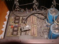
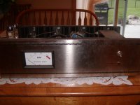
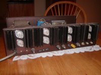
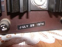
A few pictures of one that has not had the best of care.
Wow, that's even dirtier than my Tiger! I agree that Meyer was way ahead of his time and IMHO his amps were competitive with most anything else around at the time. The '70s weren't the best of times for solid state sound quality and the Tigers did sound good.
My Tiger folder (a paper one) has the original Tiger, plus variations with and without protection and the .01, which I think was also labeled #175 and #175A, should anyone need a copy. There was also a 4-channel circuit that I only have the schematic for. Though I thought about building a Tigersaurus, I could never quite justify it.
For many years my only signal source for testing was the little plastic boxed SWTPco 3038-based function generator. It was a super bargain at the time.
I remember being quite sad when I heard of Meyer's death quite a few years ago.
It would certainly be interesting to build an updated Tigersaurus. I considered the same for the Tiger, but I'm afraid I'd make so many changes that it would be the same amp only in name.
I'd like to thank PB2 for starting this thread. Its been enjoyable for me to read something positive about the Tigersaurus amps for once.
quote:It would certainly be interesting to build an updated Tigersaurus. I considered the same for the Tiger, but I'm afraid I'd make so many changes that it would be the same amp only in name.
Just out of curiosity what would you change and what would you leave alone if I may ask?
quote:It would certainly be interesting to build an updated Tigersaurus. I considered the same for the Tiger, but I'm afraid I'd make so many changes that it would be the same amp only in name.
Just out of curiosity what would you change and what would you leave alone if I may ask?
Noticed a typo in my last post- obviously it should be 8038, not 3038!
I actually like the gain of the Tiger output stage and would like to keep it, but I think that configuration is the source of increasing distortion and current consumption at high frequencies, as all the previous discussions show. To me however, that output stage is what makes a Tiger a Tiger.
Everything left of the original Q5/Q6 drivers (original Tiger schematic) I'd replace with a fairly simple Self-based design like the one I did at the bottom of this post. He showed that more complexity doesn't buy that much. I don't fully grasp the double diff front end in the #207/#275/Universal B as well as I do the simple Self design (he may have covered the one used in the B, but I wasn't paying attention.)
So, I'd try the original output section with a Self-based front end. If it still had a tendency to short the supplies, I'd have to try some of the fixes discussed here or in the other Tiger thread, but that's where it would likely lose any semblance of a Tiger.
I was just looking at my notes from fooling with the Tiger and it seems the original feedback cap was specified as 220 pF. I reduced this to 50 pF. I tried a B-C cap around Q3, which improved measured specs and stability but oddly enough made the amp sound dead. Bad idea. The original C2 electrolytic on the feedback network is, at least in my circuit diagrams, installed backwards. There's a slight bias voltage and it should be ground side to ground, not as shown. It's also not large enough (220 uF), as it causes a slight roll-off at 20 Hz.
The bias network consisting of a couple 1N3754 diodes actually works well. I'd be interested in comparing that with the more common VBE multiplier. Being bypassed it shouldn't matter, but who knows? I'm probably biased as I still have some 1N3754 diodes stashed away.
Last edited:
In the blameless design I referred to above, I did a lot of experimentation with output inductors. One interesting thing, when you get down into the "blameless" level of THD, is how sensitive the numbers are to the way the output inductor is made. Winding it around anything, including the common 10 ohm carbon resistor, is measurably worse than a true air core. I ended up turning some small polycarbonate bobbins just for this purpose, and positioned them for minimum interaction.
I think there are three threads going on Tiger related amps, but I'll toss this out here as it probably applies to all. My success with the Tiger amps may be closely related to being conservative with supply voltage. The devices don't have much safety margin, at least not the way I like to do things. It gets even scarier when you consider where in the SOA diagram the thing can end up operating with a reactive load. Throw in a high line voltage condition at the same time and all bets are off. Another amp that suffers from the same problem is the Marantz 250- I think I replaced every device in it. Designers like the Hfe and bandwidth of lower voltage devices and probably tend to go for overall performance rather than covering a worst case condition of high line voltage, Deep Purple and an excess of beer.
I think there are three threads going on Tiger related amps, but I'll toss this out here as it probably applies to all. My success with the Tiger amps may be closely related to being conservative with supply voltage. The devices don't have much safety margin, at least not the way I like to do things. It gets even scarier when you consider where in the SOA diagram the thing can end up operating with a reactive load. Throw in a high line voltage condition at the same time and all bets are off. Another amp that suffers from the same problem is the Marantz 250- I think I replaced every device in it. Designers like the Hfe and bandwidth of lower voltage devices and probably tend to go for overall performance rather than covering a worst case condition of high line voltage, Deep Purple and an excess of beer.
I know old thread but why not:
I showed that the reverse Vbe of the drivers is exceeded in the simulation - you seem to ignore that. I mentioned a long time about about the output and probably driver SOA. I have a donated Marantz 250 that is blown, the owner was not a head banger but the outputs accidentally shorted and it blew: Marantz 250M Repair After looking at the schematics, and doing some simulations of it, I would never spend the time to try to fix it given what a mess it is. It is certainly a very different topology, there is a sort of virtual ground that the input stage drives into. Still, it is a complete mess. And it does have active output stage protection - obviously it doesn't work.
I showed that the reverse Vbe of the drivers is exceeded in the simulation - you seem to ignore that. I mentioned a long time about about the output and probably driver SOA. I have a donated Marantz 250 that is blown, the owner was not a head banger but the outputs accidentally shorted and it blew: Marantz 250M Repair After looking at the schematics, and doing some simulations of it, I would never spend the time to try to fix it given what a mess it is. It is certainly a very different topology, there is a sort of virtual ground that the input stage drives into. Still, it is a complete mess. And it does have active output stage protection - obviously it doesn't work.
Last edited:
if i were to modify the Tigersaurus i will:
1. get rid of the x4 gain in the output stage..
2. this means using output devices with Vceo that can withstand 140volts or more
3. run the input stage and vas to the full rails....
end result, a BRYSTON 2B amp......
At the risk of sounding monomaniac again, wouldn't the big Tigersaurus be good candidate to modify the output into a cascoded one?
Just swap "outer" transistors "Q20, Q22" for "Q17, Q19" and vice-versa, making them run common-base, and then modify the signal path so the drivers (Sicklai) go to the "slaved" BJTs "Q16.Q18" and "Q21, Q23" in common-emiter configuration. Provided proper biasing and maybe other mods that I fail to see now, it should work. No need to get rid of the X4gain, because the amp should be hopefully stable into previous risky freq (faster output, lower Miller)...and sound good also.
But, would power headroom be compromised?
What do the experts think?
Unfortunately, I don't see any for sale at the moment...
Attachments
Hi Guys
MaxLorenz: The circuit you show already IS cascoded.
Conrad hoffman: Your blameless sims might look good but if you build it with carbon resistors you will never get that performance. To me, those amps dearly lack in high-frequency performance and never escape that lin-miller sound.
Tony Tecson: You must not be familiar with Bryston circuits, as they have a gain of three in the output stage. The Tigersouarus as shown above has a very similar topology with low-voltage input section, output stage with gain, and cascoded outputs back in that era. Bryston switched to nonCascode when suitable BJT pairs became available and very quickly went to their Quad Complementary output stage in everything larger than the 2B.
Last edited:
at the time the circuit was designed, there were no high voltage complimentary power trannies that we have now....
no use to do that circuit now, i built lots of those tigers and they can be a pain to set up...
today, there are better topologies and power trannies today than what was available to Dan Meyers at the time.....
no use to do that circuit now, i built lots of those tigers and they can be a pain to set up...
today, there are better topologies and power trannies today than what was available to Dan Meyers at the time.....
Tony Tecson: You must not be familiar with Bryston circuits, as they have a gain of three in the output stage. The Tigersouarus as shown above has a very similar topology with low-voltage input section, output stage with gain, and cascoded outputs back in that era. Bryston switched to nonCascode when suitable BJT pairs became available and very quickly went to their Quad Complementary output stage in everything larger than the 2B.
Bryston's designer would have been smart enough to properly clamp the output stage, to prevent the severe overdrive and excessive reverse vbe. And not to use a dinky TO-5 to drive two pairs of high power outputs.
There are more modern output stages with gain that have good reliability records. Ther have a few more parts in them (diodes) and TO-220 drivers.
The problem with cascoding is that if the output stage misbehaves, you won't get a nice voltage division between master and slave outputs. You have to either prevent all possible misbehaviors, or use devices rated a lot more than half the supply. The more common EF3 cascode is a lot less susceptible to problems.
Hi Guys
MaxLorenz: The circuit you show already IS cascoded.
Sorry, I probably missunderstood the signal path...
Thank you Mr. PB2 for the clarification.
Anyway, it could be modded as true cascode, for extended freq. response and hopefully more stable work and surely even better sound.
On another note, I found a recommendation for common-emitter output amps to connect the drivers to output node to reduce risk of oscillation AND with a reference to Tiger amps:
The Leach Amp - Output Stage
Though I do not completely understand cascodying (nor CFP for that matter) detailed working principle, I am actively experimenting with CFP-cascoded input, cascoded VAS, plus cascoded pre-drivers and CFP-cascoded -CFP outputs in my AMNESIS amp thread, and I tell you that is barely stable but the sound is nothing but marvelous...ghostly at times. even with low Q test equipment.
That is why I keep trying...perhaps Mr. PB2 you could take a look at it and advice???
The AMNESIS amp: a good amplifier, like a gentleman, has no memory.
Thanks in advance.
Sincerely yours,
M.
Last edited:
Guys,
Look at q16/18 and 21/23.
They are tied bases and tied emitters. They do not current share properly. To do it right, break the emitter ties add two more 100's. Also, the r 14 10k needs to be half watt, not quarter. IIRC, it dissipates 300 plus mW.
I beat the livin day lights out of four of them feeding speaker lab k horns, only had one problem. It popped all the tweeter caps at a gig for a birthday party. When they blew, two of the bodyguards opened their jackets, my friend told me do not move. Turned out it was line cord ground loop related.
I agree the 40409 and 40410's were wimpy, but never popped one. Also, mine had mj15000 series outs IIRC. But I also built two into a 3ru chassis with a high cfm 5 inch fan and major heat sink sets built as a tunnel.
Jn
Last edited:
- Status
- This old topic is closed. If you want to reopen this topic, contact a moderator using the "Report Post" button.
- Home
- Amplifiers
- Solid State
- SWTPC Tigersaurus 250W Amp Simulation