Terranigma, what was the highest rail voltage you tried with HexFet circlophone version? 50V ?
I said that I used 50V rails with my Hexfet build earlier but it appeared to be 45V. Sorry for my bad memory. I changed my LTP transistors with high HfE BC550C's accordingly since they are 45V rated. This is the highest rails that I can afford now.
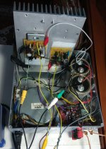
I guess I could test up to the 65V region if I have a suitable transformer but the HEAT dissipation should be considered seriously at this level (you already know this). The big heatsink in the photo is barely handling a single channel at full power. It can handle both channels at moderate listening levels.
Attachments
Elvee seems busy for a while so let me give you a tip until he arrives. Measure the voltage across the 1ohm resistor (R8) in milivolts range, it is the exact value of the quiescent current in miliamps. From my experience it should be between ~160 and ~200.
Regarding C12, you should use an even lower value like 180pF with 2N3055's. (read post #56).
Very comprehensive info from Elvee and thanks to you for posting
") . I will be building as per post #1 sch here Building Elvee's Circlophone: Documentation, Parts, Accessories, & beginner friendly with , only changes being 32V rails and with MJL21194 (TO-264) , 2x15V zeners and 43k resistor R21..
. I will be building as per post #1 sch here Building Elvee's Circlophone: Documentation, Parts, Accessories, & beginner friendly with , only changes being 32V rails and with MJL21194 (TO-264) , 2x15V zeners and 43k resistor R21..I am not sure if its right config and compensations. Sorry, too much info and less time to read because of WFH are all ruining DIY experience.
Very comprehensive info from Elvee and thanks to you for posting
I am not sure if its right config and compensations. Sorry, too much info and less time to read because of WFH are all ruining DIY experience.
R21=47K is correct for 30-35V range.
R21 vs Vs chart is below:
25V : 33K
25-30V : 39K
30-35V : 47K
35-40V : 56K
40-45V : 62K
45-50V : 68K
Here is some brief info:
Q13, VAS (Q5, Q6), Drivers, Outputs: Vce > 2Vs
Other transistors: Vce > Vs
If you're going to use single zener, it must be 1/2 Watt at least.
C12 is mostly safe at ~180pF for output devices Ft < 5MHz (2N3773, 2N3055, MJL21194, MJ15003 etc.)
C11 is needed if going to use faster devices (2SD1047, BDY58 etc.).
Q5 and Q6 specs are very important on sound character. Find ones with Ccb(Cob) minimum 4.7pF, maximum 15-16pF and minimum Ft 80-100MHz at 10mA. You will encounter recessed trebles with slower devices.
Check DC offset before connecting speakers. Circlophone is generally produces very low DC offset if LTP transistors HfE is close. Matching is not mandatory. When I match LTP transistors, DC offset is generally at -3 to 3 mA range.
Last edited:
Thanks Terra for ensuring the interimElvee seems busy for a while so let me give you a tip until he arrives. Measure the voltage across the 1ohm resistor (R8) in milivolts range, it is the exact value of the quiescent current in miliamps. From my experience it should be between ~160 and ~200.
Regarding C12, you should use an even lower value like 180pF with 2N3055's. (read post #56).
.Yes, it is correct. Changing C12 should normally not directly impact the quiescent dissipation (unless something is oscillating, which is unusual)
Thanks Mr Elvee. My prototype with 14-0-14 V AC transformer is dead silent without connecting any input. No motorboating and no oscillations. I donot any any oscilloscope at home but the sound is crystal clear without distortion. I have matched gain of input transistors and also that of 2N3055. I will try to measure quiescent current as suggested.

Dear Mr Elvee,
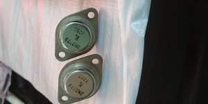
One channel of Circlophone with 2N3055 @ 14=0-14 AC transformer is working very good. I have received a Toroidal transformer 24-0-24 AC. I therefore want to cahnge the output transistors to a higher voltage Vce. I had purchased three 2N3773 a long back in the year 1980. They have not been used as yet. Their make seem unknown to me. It is stamped "K". As far as I remember it could be "Steel". However I am attachind photo. I need your advice.
One channel of Circlophone with 2N3055 @ 14=0-14 AC transformer is working very good. I have received a Toroidal transformer 24-0-24 AC. I therefore want to cahnge the output transistors to a higher voltage Vce. I had purchased three 2N3773 a long back in the year 1980. They have not been used as yet. Their make seem unknown to me. It is stamped "K". As far as I remember it could be "Steel". However I am attachind photo. I need your advice.
Attachments
Dear Mr Elvee,
This question is just for academic interest. I am getting an DC output offset voltage of around + 4 mV varying from 3.75-4.5 mV.
Gain of following transistors have been matched:
Q1 to Q4 & Q7 - BC 556
Q5 & Q6 - 2SC2621
Q12 & Q13 - 2N5551
Q9 & Q11 - BD139
Q8 & Q10 - 2N3055 (old version Vce 60V)
I do not understand why this offset value is appearing. Theoratically it should be 0 mV. I forget to check metal film resistors, may be these are resulting offset voltage.
However what offset voltage should ideally appear in Circlophone built as per original schematic.
Thanks
Katiyar
India
Your DC offset is very optimum and not that easy to achieve in most designs without some extra measurements like DC servo etc.DC output offset voltage of around + 4 mV varying from 3.75-4.5 mV.
This one has 5pF Cob which seems nominal. I think you can use these without extra capacitance between B-C. Ft is 80MHz at 10mA which is minimum optimal too.Q5 & Q6 - 2SC2621
Q9 & Q11 - BD139
I think this is a typo. Original BJT version uses PNP drivers (BD140). BD139 is NPN complementary of BD140.
Dear Mr Elvee,
This question is just for academic interest. I am getting an DC output offset voltage of around + 4 mV varying from 3.75-4.5 mV.
That's the typical offset level of an untrimmed opamp, like the µA741, TLO71, etc.
These opamps use inherently matched components since they are monolithic.
Achieving the same performance level using hand-matched components, without resorting to trimming is exceptional, so you have nothing to worry about.
If an ultra-low offset was a design requirement, we could chase second order sources, make multidimensional matching, etc., but really for an amplifier anything lower than 50mV is OK, and <20mV is stellar.
You did your homework perfectly, and there is no need to go further
Thanks.
Q9 & Q11 are BD140. Most active components are from CDIL, a reputed manufacturer and exporter of electronic components. Q12 & Q13 are from KEC. Output transistors 2N3055 are from BEL.
Now with the results achieved, I am excited to build two modules for a stereo version.
Q9 & Q11 are BD140. Most active components are from CDIL, a reputed manufacturer and exporter of electronic components. Q12 & Q13 are from KEC. Output transistors 2N3055 are from BEL.
Now with the results achieved, I am excited to build two modules for a stereo version.
Terranigma, what was the highest rail voltage you tried with HexFet circlophone version? 50V ?
Hi Minek,
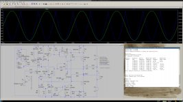
I think you asked because of your failed simulations of hexfet Circlophone on builders thread. Probably the cause of the failure was the P-channel hexfets at output as Elvee mentioned.
When I refer to mosfet/hexfet Circlophone it is an "inverted" version which allows you to use N-channel mosfets. I simulated N-MOS version so many times and never had such an issue, even with much higher rails.
Attachments
Yeah, that's what I ended up doing - inverting the schematic, even if it didn't look 'natural' to me.
Eventually it worked perfectly.
I can even reuse my PCBs, just change polarity of everything..
Still have plans to build HexFet circlophone, that would be my third
First two BJT circlos still running very nicely.
I see you have nice CCS instead of R21. I also used CCS, but simpler one...
Eventually it worked perfectly.
I can even reuse my PCBs, just change polarity of everything..
Still have plans to build HexFet circlophone, that would be my third
First two BJT circlos still running very nicely.
I see you have nice CCS instead of R21. I also used CCS, but simpler one...
Still have plans to build HexFet circlophone, that would be my third
When you do, you can consider Fujitsu mosfets. When I look at their datasheets, I'm quite surprised. They have high transconductance, low capacitance and low thermal resistance (even TO220 ones). I think they are not so popular on audio because they have no P complementaries. Since we have Circlophone, who cares? Example ones: 2SK3549, 2SK3678, 2SK3533, 2SK3875
I'm not an electronics designer. Such ideas that mentioned in thread is the sole way to put something on my behalf.I see you have nice CCS instead of R21. I also used CCS, but simpler one...
- Home
- Amplifiers
- Solid State
- ♫♪ My little cheap Circlophone© ♫♪