Thanks, Perfect then! gonna order that set and worry later how to get things connected and adjusted... Probably gonna make my own thread to not post losts of newbie questions here.
Regarding my mother has recently made a ground connection in her house for a ceramic cooking oven i´m gonna make this amp there with help of someone more experienced in electronics so risks are reduced at minnimun. News will be posted!
Regards.
Regarding my mother has recently made a ground connection in her house for a ceramic cooking oven i´m gonna make this amp there with help of someone more experienced in electronics so risks are reduced at minnimun. News will be posted!
Regards.
There is also a build thread, with lots of practical information:
https://www.diyaudio.com/forums/sol...-beginner-friendly.html?highlight=circlophone
https://www.diyaudio.com/forums/sol...-beginner-friendly.html?highlight=circlophone
The practical difference would be tiny, but the cascode reference should definitely be tied to the output (from a theoretical perspective).
The subject has already been discussed here:
♫♪ My little cheap Circlophone© ♫♪
And here:
♫♪ My little cheap Circlophone© ♫♪
And probably elsewhere too, but you get the idea
The subject has already been discussed here:
♫♪ My little cheap Circlophone© ♫♪
And here:
♫♪ My little cheap Circlophone© ♫♪
And probably elsewhere too, but you get the idea
Hi Elvee,
I am now very much convinced that circlophone is one great design and offers musical bliss, very near to my everfavourite JLH69. Recently I did a AB comparison with JLH69 and circlophone ( standard circuit, with TIP3055 output). I would say the Circlophone approaches Jlh sonics almost 95 percent,the small deficit is my perceived lack in the highs.( Noticeable only on AB comparison) Otherwise, as I previously posted, Circlophone Rocks!!.Now, I would like to build another circlophone,this time with powwrflux layout.. I plan to use 2sd1047 as the outputs. Can I expect a better high frequency performance when compared to TIP3055?
Second, Given a lot of positive response for the subjective musical perception by all the builders, can I request a FFT of the circlophone with FFT of a JLH 69? Say at 1khz and 1 watt output? It's just to reaffirm that whether the Extremely pleasing sonics are due to the harmonic spectrum distribution.Apologise if such a comparison has already been done, I read many times thorough the forum and I could not locate a FFT graph...or may be I missed something?
Yes, it is several times faster than the 3055Can I expect a better high frequency performance when compared to TIP3055?
Here is the comparison, in sim because I don't have a JLH handy and my means of spectrum analysis are limited at the moment.Second, Given a lot of positive response for the subjective musical perception by all the builders, can I request a FFT of the circlophone with FFT of a JLH 69? Say at 1khz and 1 watt output? It's just to reaffirm that whether the Extremely pleasing sonics are due to the harmonic spectrum distribution.Apologise if such a comparison has already been done, I read many times thorough the forum and I could not locate a FFT graph...or may be I missed something?
Both circuit are the plain vanilla versions, 1W/8ohm
Attachments
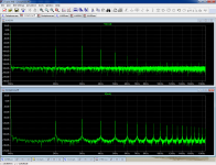
There are probably a number of things to consider: first, the harmonic profile of the JLH may be more attractive, at least in relative terms, perhaps because the JLH is not symetrical, unlike the C.
The C is probably one of the most symetrical amplifier currently available, despite its superficial look.
Openly symetrical amplifiers like the symasym are in fact less symetrical, because they rely on complementarity, which is never perfect whereas the C uses identical transistors in a "horizontal" symetry rather than a vertical one.
This symetry mostly eliminates certain categories of harmonics, mainly even-ordered ones, and also favors interactions between those remaining.
The result is an overall reduction of THD, and an apparently extended spectrum.
Apparent, because the absolute level of higher order harmonics is completely insignificant, even if you don't believe in masking effects.
The scale of the two graphs is misleading, because the LTspice autorange opted for a 30dB lower floor for the C, which changes the perspective.
We also have to take sims and even measurements with a pinch of salt: when you arrive at -120dB, a tiny detail can change everything: in particular the matching, which determines the symetry.
Even if you match all the transistors of a C, it won't be perfect, and some of the higher harmonics of the sim will vanish, to the expense of lower order ones.
The result will be a slightly higher global THD level, and a more pleasing profile -superficially and visually, at least-.
Remember that you don't hear with your eyes, and that large scale, blind tests show that the general population tends to prefer a completely neutral, distortionless and flat reproduction rather than "engineered" concotions.
This is why I try to adhere to relatively simple, objective principles.
People like tube sound, especially for instruments, digital effects, frequency enhancements but for general reproduction, a completely neutral system is probably optimal: you can always add enhancements and corrections where needed.
If your amplifier already has a character, it cannot be undone.
Dear LV,
Ref to your single supply mod as given in post 901, https://www.diyaudio.com/forums/solid-state/189599-little-cheap-circlophone-post3011393.html:
Has any body built it and any specific recommendations ?
Anybody developed a pcb layout for that single supply mod ?
--gannaji
Ref to your single supply mod as given in post 901, https://www.diyaudio.com/forums/solid-state/189599-little-cheap-circlophone-post3011393.html:
Has any body built it and any specific recommendations ?
Anybody developed a pcb layout for that single supply mod ?
--gannaji
There are probably a number of things to consider: first, the harmonic profile of the JLH may be more attractive, at least in relative terms, perhaps because the JLH is not symetrical, unlike the C.
The C is probably one of the most symetrical amplifier currently available, despite its superficial look.
Openly symetrical amplifiers like the symasym are in fact less symetrical, because they rely on complementarity, which is never perfect whereas the C uses identical transistors in a "horizontal" symetry rather than a vertical one.
This symetry mostly eliminates certain categories of harmonics, mainly even-ordered ones, and also favors interactions between those remaining.
The result is an overall reduction of THD, and an apparently extended spectrum.
Apparent, because the absolute level of higher order harmonics is completely insignificant, even if you don't believe in masking effects.
The scale of the two graphs is misleading, because the LTspice autorange opted for a 30dB lower floor for the C, which changes the perspective.
We also have to take sims and even measurements with a pinch of salt: when you arrive at -120dB, a tiny detail can change everything: in particular the matching, which determines the symetry.
Even if you match all the transistors of a C, it won't be perfect, and some of the higher harmonics of the sim will vanish, to the expense of lower order ones.
The result will be a slightly higher global THD level, and a more pleasing profile -superficially and visually, at least-.
Remember that you don't hear with your eyes, and that large scale, blind tests show that the general population tends to prefer a completely neutral, distortionless and flat reproduction rather than "engineered" concotions.
This is why I try to adhere to relatively simple, objective principles.
People like tube sound, especially for instruments, digital effects, frequency enhancements but for general reproduction, a completely neutral system is probably optimal: you can always add enhancements and corrections where needed.
If your amplifier already has a character, it cannot be undone.
Well explained.Many Thanks.
Circlophone finally built
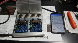
I finally managed to build Elvee's circlophone.
MJ21194 (output)
KSA1381 (drivers)
TTC004B (vas + cascode instead of zeners)
R21 replaced with current source
all small PNP: KSA992, NPN: KSC1845
So far I've been running one channel with +/- 25V rails, as drivers and VAS
(mounted on the same, tiny heatsink) are running hot (64 degrees C).
Need to add bigger heatsink for them, especially for 50V rails, as I planned..
Speaker is dead silent, no hum or thump; music plays perfect, output DC:
0mV when cold, settles at 7mV when hot.
Once heatsink is increased, will do measurements with oscilloscope,
and will try increase rail voltage. My PSU is +/- 50V..
Attachments
Last edited:
Once heatsink is increased, will do measurements with oscilloscope,
and will try increase rail voltage. My PSU is +/- 50V..
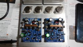
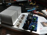
Here is bigger heatsink. Now temp is 54 C.
Still one channel only, so with 2nd channel it will get hotter.
Running at 35V rails. Been playing music for the last 3 hours, everything
seems to be OK.
Wondering, how hot these drivers will get at 50V rails....
Attachments
Beautiful build!
Each will dissipate a little under 2WWondering, how hot these drivers will get at 50V rails....
Beautiful build!
Each will dissipate a little under 2W
These are TO-126 devices without metal tab, it's all plastic...
Not sure if they can do 2W...
Any suggestions?
Been running it with bigger heatsink for 2 hours, at 45V rails.
Hot, but below 65 C - but 2nd channel will share the same heatsink.
Also, current source small NPN (R21 replacement) runs hot (~ 50 C), guess in the next build MJE device will be better...
What is the highest practical safe temperature (case/heatsink) for
these devices?
Last edited:
1 to 1.5W without heatsink, up to 7W with heatsinkThese are TO-126 devices without metal tab, it's all plastic...
Not sure if they can do 2W...
Using a non-isolated TO126 with silpad or a TO220 on the same kind of heatsink will not change the situation a lot, because the interface plays a relatively minor role with a smallish heatsink, thus if you really want to improve matters you need lower Rth devices AND bigger heatsink, but I don't think it is necessary.Any suggestions?
Try to measure the actual temperature of the heatsink in a situation as close as possible to the final configuration: if it is <80°C, you should be OK, between 80 and 100°C, it begins to be seriously hot, and if >100°C, pull the plug and start afresh.Been running it with bigger heatsink for 2 hours, at 45V rails.
Hot, but below 65 C - but 2nd channel will share the same heatsink.
It should dissipate around 150mW, which will make it warm(ish), but no cause for concern since a TO92 can dissipate between 300mW and 1W, depending on the typeAlso, current source small NPN (R21 replacement) runs hot (~ 50 C), guess in the next build MJE device will be better...
What is the highest practical safe temperature (case/heatsink) for
these devices?
Try to measure the actual temperature of the heatsink in a situation as close as possible to the final configuration: if it is <80°C, you should be OK, between 80 and 100°C, it begins to be seriously hot, and if >100°C, pull the plug and start afresh.
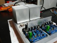
OK, running at 50V rails, with heatsink beefed up even more with 4 clip-on additions. It looks like they are helping a lot.
Both channels running, 50V rails, 68 degrees C on the heatsink so far (after 10 minutes).
Also output transistors are getting warmer now.
Each channel draws 270mA at idle.
4-5 mV at the output (input pair was matched almost perfectly)..
Attachments
Try to measure the actual temperature of the heatsink in a situation as close as possible to the final configuration: if it is <80°C, you should be OK, between 80 and 100°C, it begins to be seriously hot, and if >100°C, pull the plug and start afresh.
Few things I learned:
a) Circlophone is not "little" - it actually has 'normal' number of components/devices, especially when compared with 'prehistoric' kinds of amps
b) it's also not "cheap" - especially heatsinking. Unless one happens to have drawers full of old stuff (like original 2N3055s) and scarps of thick Alu profiles gathering dust in the garage
c) "warm" class AB actually means "very hot" class AB. Good thing winter is coming soon.
d) my PCB design assumed much cooler temperatures, otherwise I would mount all transistors on the main heatsink.
e) good thing - everything worked from the first moment. Turn on the power, and it played music like a champ! No adjustement needed.
Kudos to Elvee!
Last edited:
With both channels running for 3 hours (idle), with rails 50V, temperature of the heatsink (drivers + vas) rises to 83 C.
Main heatsink for output transistors runs at 50 C.
Not sure if my infrared termometer works correctly - it gives higher temperature readings on black/dark surfaces, and lower readings on shiny aluminum surfaces..
83 degrees is measured on black anodized clip-on heatsinks.
Both channels draw 570mA, so at +/-50V that's 50W of power going into the heat..
I guess I'll have to run at lower rails voltage..
- Home
- Amplifiers
- Solid State
- ♫♪ My little cheap Circlophone© ♫♪