I totally agree on this....
This way we can also remove the input capacitor...with the risk to introduce DC offset if the source is poor...
This is also the version i currently have running in my simulator...(sims really good...2.harmonc at -110 dB..and higher order barely existing
This way we can also remove the input capacitor...with the risk to introduce DC offset if the source is poor...
This is also the version i currently have running in my simulator...(sims really good...2.harmonc at -110 dB..and higher order barely existing
MiiB
Nice. You have our circuit in mind.
It is good to have you. I have learnt a few things from you.
Hope to see someone bias 2SK170 from negative supply rail.
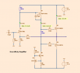
In the meanwhile a diagram for mikelm.
It was long ago I posted it for swordfishy
But it is so nice. Isn't it ...............???
mosfet VAS is back
Nice. You have our circuit in mind.
It is good to have you. I have learnt a few things from you.
Hope to see someone bias 2SK170 from negative supply rail.
In the meanwhile a diagram for mikelm.
It was long ago I posted it for swordfishy
But it is so nice. Isn't it ...............???
mosfet VAS is back
Attachments
SWF,
I think the stability is quite good, but, the ongoing, undamped overshoot concerns me.
First up, try about 47pF from drain of the VAS to the jfet source, and if that is not sufficient, add a 10pF silver mica miller cap across gate/drain of the VAS.
I hope this scotches the overshoot... and it should also improve the sound quality further.
Thanks, saw the 3.42V bias voltage; that presumably is around 1.7V Vgs for each output device.
Congratulations to Lineup for a great topology, thanks mate!
Cheers,
Hugh
A second solution to stability issue is a cap from vas drain to output.
with resistive load you will have unity gain. but with a capacitive load it will start working as the gain fall below unity.
try 470pf - 2.2nf.
It works well.
Last edited:
This is what I'am currently thinking....Higher power version Hawksford cascode..and two sets laterals..LED biased current sources...Simple circuit... hopefully some builders...")
Distortion is so low it's hardly worth mentioning at -115 dB 2. order...at+/-25 V..output-swing..
Distortion is so low it's hardly worth mentioning at -115 dB 2. order...at+/-25 V..output-swing..
Attachments
Now, if you get your DC-coupled Fetzilla to work
I will be even happier.
I am looking for the parts now but may take a while, but I will definitely build the DC linked version.
thx for the spice model
mike
Wise words clearly based on a lot of experience.
Lineup,
I appreciate your goodwill, and careful sponsorship of this thread. SWF is a 31 year old jumping out of his skin with different circuits and tweaks every hour of the day, hell, I was like that once... I see this as a learning exercise. His input is pivotal and much welcomed.
You correctly identify my approach, and fearlessly describe your own. Both approaches are valid and can learn from each other.
However, the low THD approach is the conventional engineering focus and has been with us for decades. Sometimes it works, sometimes it doesn't. Often very low THD amps - the Self Blameless for example - don't really appeal in a long listening session for most audiophiles. Tastes vary. The purists, often designers, will say that they want a straight wire with gain, the amp should add nothing at all. But the majority of audiophiles, it seems to me, often with little or no knowledge of the circuitry, don't seem to like the straight wire with gain, many of them drifting across to the highly coloured tube school of audio. We can sweep aside their assessment by saying human perception is unreliable, tastes vary, people wouldn't know a good amp if it bit them on the nose, and so on. But you will find a lot of knowledgeable, thoughtful people saying that you should never buy anything without listening to it carefully, with music you know well. I second that. After all, our food, clothing, artistic and entertainment preferences are formed over a long time, and until we hear/see/smell/touch something a few hundred times, we really don't know the experience well enough to form a preference.
Therefore, we might be measuring the wrong thing, trying to assess how fast the automobile can go by reading off the licence plate....
My thoughts are that the profile of the distortion is important. For example, if the distortion is 0.05%, a highish figure, but 99% of it is H2 and H4, it will probably sound rather better than 0.005% where 80% of it is H5 and H7. Jean Hiraga first noted this in the sixties. Earl Geddes with his Gedlee Index has formalised this observation, and takes weighted, high account of odd order distortion artefacts. Absolutely nothing is new under the sun.
Furthermore, lots of loop gain means that while the distortion artefacts, taken individually, are reduced in amplitude, they increase in number, and trail on until at least the 25th harmonic, particularly beyond a loop gain of about 40dB. Could it be that if we keep loop gain below about 45dB we might have better sound?
Lastly, the back emf and load phase shift of a speaker is a truly malevolent thing, and it seriously disrupts the feedback mechanism, causing correction to be phase shifted radically from the input. This confuses the amp, which cannot distinguish between its distortion/phase shift and that of the speaker to which it is corrected. You could argue this is the idea, but there is no doubt that the reactive speaker load seriously destabilises amplifiers. Again, this problem is ameliorated by reducing loop gain.
Hugh
mmmm - interesting reading this again in light of swordfishy's latest version because that does have very low distortion indeed, so I expect the sound will be more neutral than warm . . . but the larger VAS mosfet does roll off OLG more than anything I've tested in spice to date - so perhaps it has the best of both approaches.
I never expected to see a feedback amp with a Push Pull o/p that can operate with normal loads without any compensation - truly a step forward.
p.s. does anyone know where I can buy 2sk170's or Lsk170's in europe ? the ones I have will probably only arrive in about six weeks - can't wait that long
I never expected to see a feedback amp with a Push Pull o/p that can operate with normal loads without any compensation - truly a step forward.
p.s. does anyone know where I can buy 2sk170's or Lsk170's in europe ? the ones I have will probably only arrive in about six weeks - can't wait that long
Last edited:
Wow, this has moved along......
Brief comment on the fb resistor: it does not destabilise anything at all. By using the series fb resistor to set up the DC operating conditions of the amp we actually simplify the circuit. In practice, it will have an almost constant DC current through it, fixed by R4, the source/gate resistor of the VAS.
Idss for the 2SK1780 is listed as ranging from 2.6ma to 20mA, in three distinct ranges. I'm hoping that SWF is using the BL series, the middle range, 8-12mA. 2/3 of the Idss is correct, but as pointed out the fact the gate bias is positive indicates either the stage current is too high or the grade of the jfet is inappropriate.
This is a low transconductance device with very low noise, around 22mS. That means Id increases by 2.2mA for each 100mV of gate potential increase. (22mA for each volt). A BF862 will therefore generate another 6dB of loop gain, and compensation might need revisiting. An increase of VAS degeneration could do this, of course.
I don't actually recommend a cap across the fb resistor to stabilise things. I prefer a combination of miller cap on the VAS, and phase lead from VAS drain to fb node. In my experience it's more predictable, more stable. It does work, but to me it's less elegant.
Mike, interesting that the mosfet VAS actually rolls off at HF!! This can only be the capacitance at the gate pulling back slew rate, but it's not what SWF found at the outset. This certainly explains why lag compensation is not required even though we have about 75dB of loop gain.
SWF, the rating of the S170 is 400mW. For reliability I gun for no more than one third of this, 135mW, so you are on the limit, particularly as your climate is subtropical. OTOH, you should try for 2/3 of Idss for best results. Fortunately, you only have low voltage across the device.
Cheers,
Hugh
Last edited:
I am still surprised that people insist on more power. You must listen at high volumes in a large room. This version with 25V rails is more than enough to make my workshop uncomfortable to be in, and my speakers have only average sensitivity. I literally have to stand at the door for listening tests. I would rather keep the same rail voltage and up the bias current. The sound just gets sweeter and sweeter with more current.
Also, regarding lower distortion, while it is nice to try and get lower and lower from a purely academic and aesthetic point of view, I can say that the distortion of the current circuit is already quite low. Any that is there is augmenting, not detracting from the sound. I actually would prefer not to lower the distortion at the cost of extra devices, though the circuits that are being posted are all very inspiring.
I am perfectly happy with it the way it is! This is obviously just my opinion and I encourage you all to experiment and provide your feedback and listening impressions.
I am saying this because I have a Doug Self Blameless Amplifier and I hate the sound so much it is on ebay for half of its original $3k price tag. Personally, I think Hugh has the right idea.
Having built lineup's original circuit I prefer the version without the CCS in the input, but it will be interesting to see what everyone else thinks.
Lineup,
I actually tried removing the Feedback Cap yesterday and had some pretty bad DC offset issues. Not sure if this will apply with the CCS version, but it was pretty terrible with the front bias version.
Yes, but back then I was using the ZVP3310A, a much smaller TO92 device compared to the TO220 IRF9610. I assume the gate capacitance was much smaller too?
Hugh, I actually have both current classes of JFETs (the higher class is still coming), so it will be interesting to experiment. Indeed, I do need to reduce the current.
I set up the schematic yesterday without really tweaking the resistor values and was so gob smacked by the results i had to post the schematic before I had checked everything was running within spec.
I hope to try your suggestions for removing the overshoot over the coming days.
Also, regarding lower distortion, while it is nice to try and get lower and lower from a purely academic and aesthetic point of view, I can say that the distortion of the current circuit is already quite low. Any that is there is augmenting, not detracting from the sound. I actually would prefer not to lower the distortion at the cost of extra devices, though the circuits that are being posted are all very inspiring.
I am perfectly happy with it the way it is! This is obviously just my opinion and I encourage you all to experiment and provide your feedback and listening impressions.
I am saying this because I have a Doug Self Blameless Amplifier and I hate the sound so much it is on ebay for half of its original $3k price tag. Personally, I think Hugh has the right idea.
Having built lineup's original circuit I prefer the version without the CCS in the input, but it will be interesting to see what everyone else thinks.
Lineup,
I actually tried removing the Feedback Cap yesterday and had some pretty bad DC offset issues. Not sure if this will apply with the CCS version, but it was pretty terrible with the front bias version.
Mike, interesting that the mosfet VAS actually rolls off at HF!! This can only be the capacitance at the gate pulling back slew rate, but it's not what SWF found at the outset.
Yes, but back then I was using the ZVP3310A, a much smaller TO92 device compared to the TO220 IRF9610. I assume the gate capacitance was much smaller too?
Hugh, I actually have both current classes of JFETs (the higher class is still coming), so it will be interesting to experiment. Indeed, I do need to reduce the current.
I set up the schematic yesterday without really tweaking the resistor values and was so gob smacked by the results i had to post the schematic before I had checked everything was running within spec.
I hope to try your suggestions for removing the overshoot over the coming days.
Last edited:
Yep, the IRF9610 has no less than 170pF of Ciss, pretty high.
I note it can do 200V and 2A to 20W, that's a serious device. The curves look quite non-linear at very low currents. I wonder if there are other mosfets which can do no more than say 500mA, with all other characteristics similar and a lower Ciss?
That might sound better, but then, it might need quite a bit of compensation, too. Might check Siliconix, they have some smaller ones.
The bootstrap will bring much more current variation in the VAS, which in turn will boost lower order harmonics, chiefly H2, H3 and H4. It also relaxes the compensation issues because of the inductance of the bootstrap cap. However, you may not prefer the sound; I like it, but tastes vary.
Hugh
Last edited:
Swordfish...
The reason for the quest for higher power is quite simple....When you run a pair of Raidho C-4 in maybe 200 square meter room...you just need more power..actually it's not the SPL that makes the sound loud...it's the distortions that comes with the higher sound pressure...And with more power you buy yourself some dynamic headroom that allows for greater contrasts in the music.
If you have ever heard an opera singer live or been next to a big band or a symphony orchestra..You just know that it takes more than 30 W to get at realistic levels. (if you have the speakers to go there)
The IRF 9510 has less capacitance...(still higher than the TO 92 device)
Last edited:
Swordfish...
The reason for the quest for higher power is quite simple....When you run a pair of Raidho C-4 in maybe 200 square meter room...you just need more power..actually it's not the SPL that makes the sound loud...it's the distortions that comes with the higher sound pressure...
If you have ever heard an opera singer live or been next to a big band or a symphony orchestra..You just know that it takes more than 30 W to get at realistic levels. (if you have the speakers to go there)
Fair enough, and I understand. It wasn't intended as a criticism - I just wanted to get the point across that even with 25-35 genuine clip free watts with a large enough power supply it is surprisingly capable. I tend to sit near live bands and think they sound too loud, and prefer easy going and gentle background music. The only exception is if I have had quite a few drinks to null my senses.
We have different tastes.
That said, most of my testing for this amp has been done at high volume.
The 200 square metre room you mention is probably bigger than my entire house and most people's listening rooms I would imagine! That's nearly 15 x 15m!
Last edited:
Real Performance from Kawero! and Raidho
Then you may understand... why I play with scalable designs...
BTW this playing with electronics is a hobby for me..I not in anyway trained in EE as my background is purely mechanical .where my major is vibration and materials...so playing with sand like this is for me a venture into the unknown.....but I do like to gain insights and knowledge about amplifier circuits..
michael
Last edited:
A second solution to stability issue is a cap from vas drain to output...
try 470pf - 2.2nf.
It works well.
Thanks Sonnya, I can try this tonight as I do actually have some caps lying around of this value.
I will try Hugh's method too, but I need to order the appropriate capacitors - unless I use some nasty ceramics.
Miib, nice speakers. If you are fortunate enough to be listening to those then hats off! You're clearly in the high end market, much higher than me. I hope this amplifier lives up to your expectations
Maybe one day I will sell the house and buy a pair
This thread has little to do with scalable deigns. Most people listen to music in small spaces and the equipment available for that purpose has gotten good notice. Juma has done excellent work with low wattage circuits as has lineup,and of course the Master NP. The idea of being in a 200 sq meter room with LOUD music is hardly the issue. Listening to live music and recorded music are two separate entities.
Hopefully the thread can return to the simple design that is the subject of this discourse.
Hopefully the thread can return to the simple design that is the subject of this discourse.
Yet so so little separates the two designs... only the cascode....Which I in return think is beneficial also in the low wattage design as it lowers the dissipation and allows for larger Jfet currents..and reduces higher order distortions...
And...you can with good equipment bring at least fragments of the live event into your living room...I see the recording as a code.. to restore it back you "just" need the key to unlock it...
And...you can with good equipment bring at least fragments of the live event into your living room...I see the recording as a code.. to restore it back you "just" need the key to unlock it...
- Status
- This old topic is closed. If you want to reopen this topic, contact a moderator using the "Report Post" button.
- Home
- Amplifiers
- Solid State
- JFET input, MOSFET VAS, LATERAL output = Perfect!!